 1-800-275-4576
Data Doubler
Apple Mac mini Assembly Manual & User Guide
Introduction
1.1 Hardware Compatibility
Host Computer Compatibility
- Apple Mac mini 2010, model identifier Macmini4,1
- Mac mini must have an optical drive (‘Server’ model not supported)
Drive Compatibility
- Any 2.5-inch SATA drive (including SSDs) up to 12.5 mm tall
1.2 Package Contents
- OWC Data Doubler kit (includes mounting screws)
- Five-piece toolkit
- Mac mini logic board removal tool
1.3 About This Manual
Images and descriptions may vary slightly between this manual and the unit shipped. Functions and features may be different from those stated in this manual. Please visit the product web page for the most recent product specifications.
Attention: Observe Precautions For Handling Electrostatic Sensitive Devices
Your computer is a static-sensitive device. It is susceptible to invisible damage if not protected during installation. We recommend proper grounding by using a grounding strap. Make sure to work in a clean, static-free area, and avoid wearing clothing that retains static charges.
Installation
2.1 Disassembling the Mac mini
Due to the number and variety of screws involved in this process, we commend you use a device to organize and keep track of the screws, such as an ice cube tray. This will help you to put the screws back in the correct locations.

1. Place the Mac mini upside down, as shown. Use a soft surface such as a towel or a mouse pad in order to protect the Mac mini from scratches.
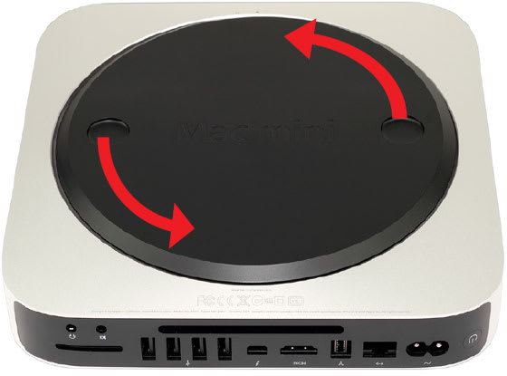
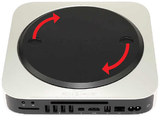
2. Rotate the bottom cover counterclockwise to the unlocked position, as shown above. There is a white dot on the bottom cover. When the bottom cover is unlocked, this white dot will line up with the corresponding dot on the aluminum housing. When the bottom cover is unlocked, press on one side of the cover to cause the opposite side to pop up, then remove it.
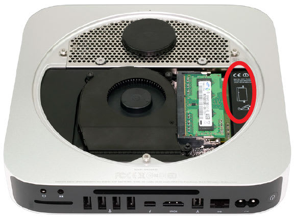
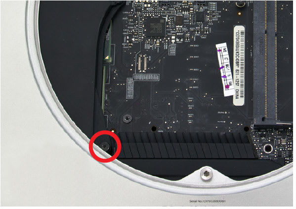
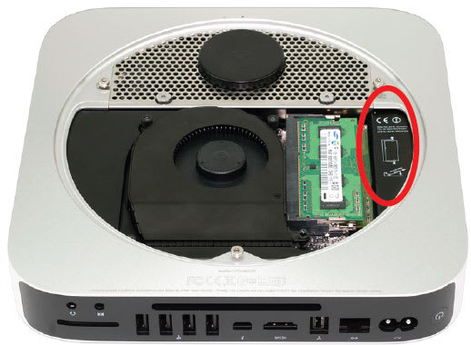
3. Remove the two memory modules. The instructions for removing the memory modules are printed directly to the right of the memory inside the Mac mini, as circled in the picture above.

4. Remove the three Torx T6 screws that secure the fan, as circled in the picture above. The two top screws are shorter; the screw on the lower right is a longer standoff screw.
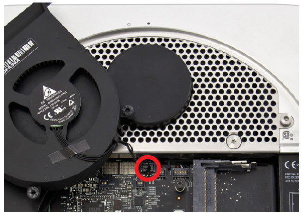
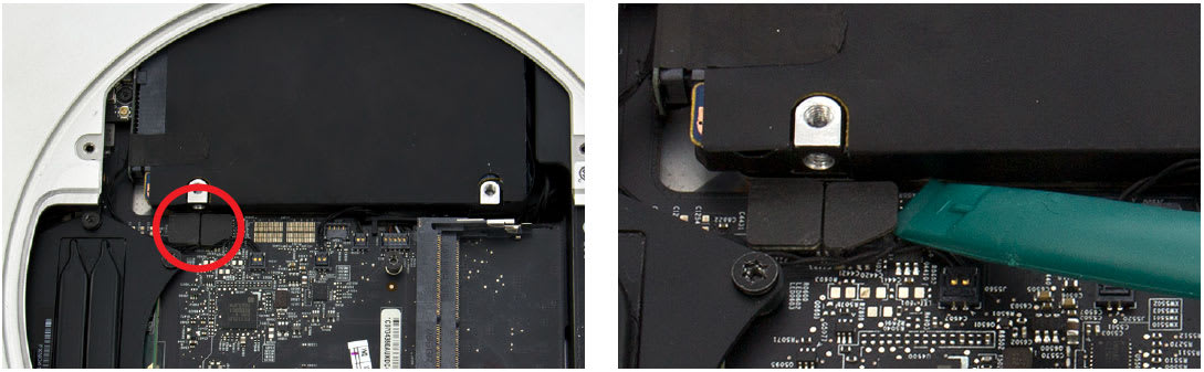
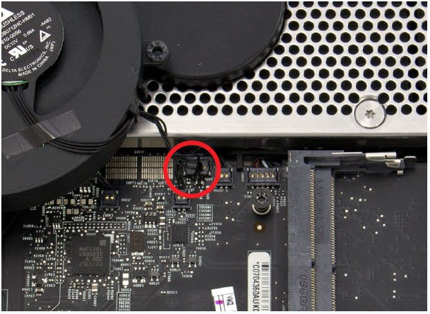
5. Disconnect the fan cable from the logic board, as circled in the picture above. The connector lifts straight up; you can use the plastic pry tool to assist.
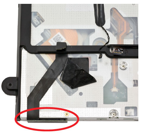
6. Remove the short T6 screw at the bottom of the black plastic cowling, as circled in the picture above.
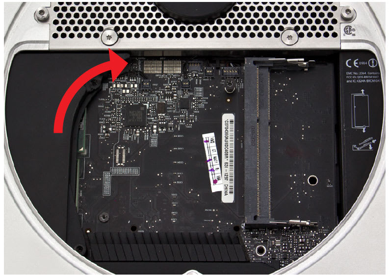
7. To remove the cowling, lift it up slightly to allow it to move clear of other hardware, then pull it out to the right, rotating the cowling slightly clockwise, as shown in the picture above. When removing the cowling, be careful not to catch it on any other hardware.

8. Use a Torx T8 screwdriver to remove the five screws circled in the picture above. The screw at the bottom and the two outside screws at the top are 2mm hex screws, but the Torx T8 screwdriver will fit. Be careful not to exert too much force on the hex screws. The two inside screws at the top are standard T8.
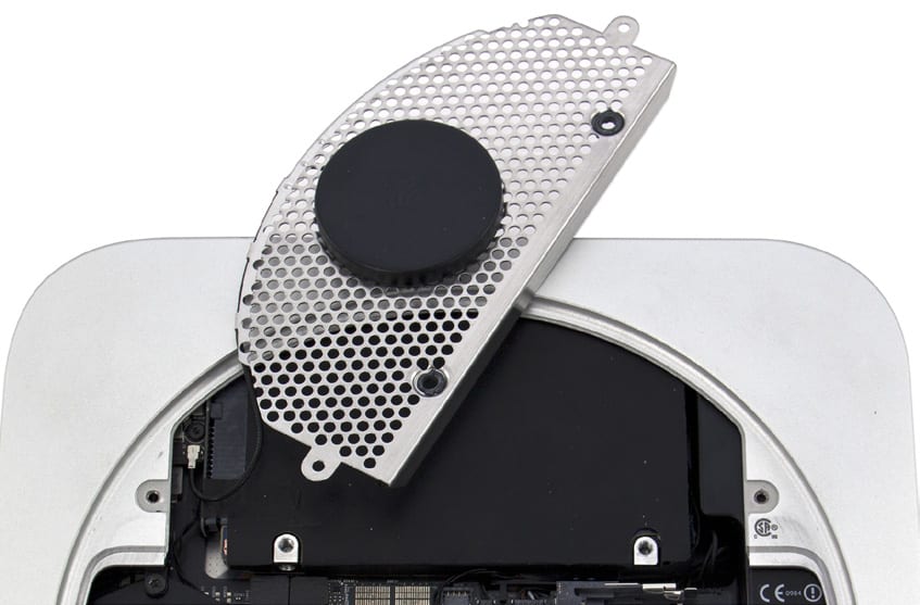
9. Lift up carefully on the antenna plate and move it slightly up and to the right in order to reveal the antenna cable attached to the wireless card, as shown in the picture above.
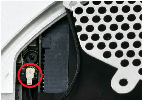
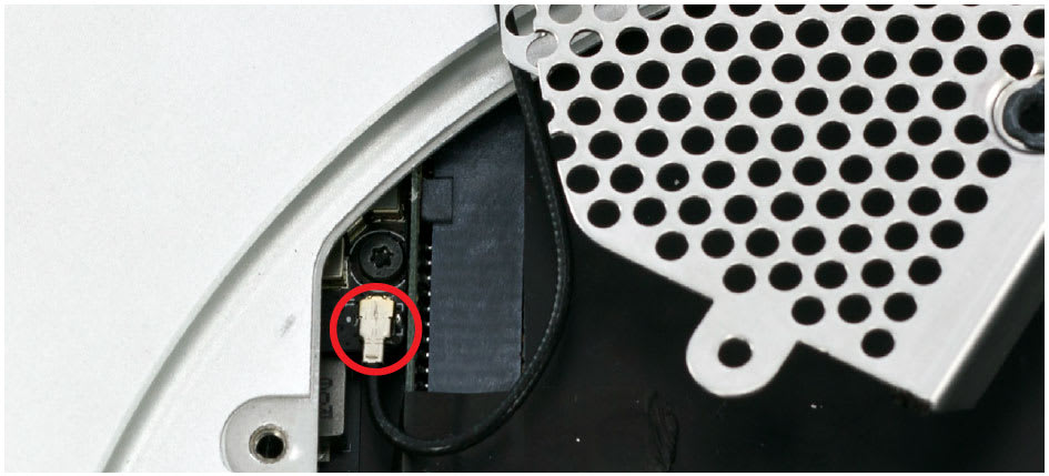
10. Disconnect the antenna cable, circled in the picture above. Be careful, as the connection is fragile and can break. Gently lift the cable connector directly up. The nylon pry tool or a pair of tweezers may help.
11. Disconnect the hard drive flex cable and the optical drive flex cable, as shown in the pictures below. Use the nylon pry tool to lift the cable connectors free from the logic board.
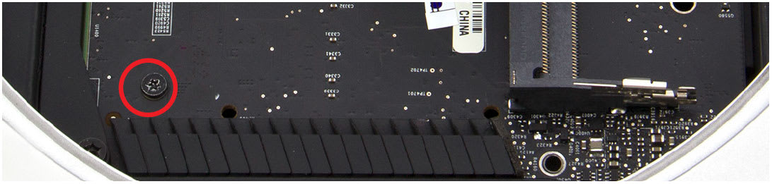
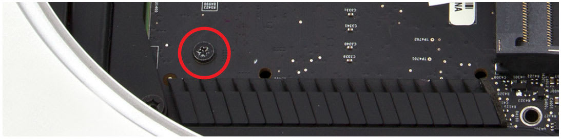
12. Remove the T6 screw at the bottom left of the logic board, circled in the picture below.
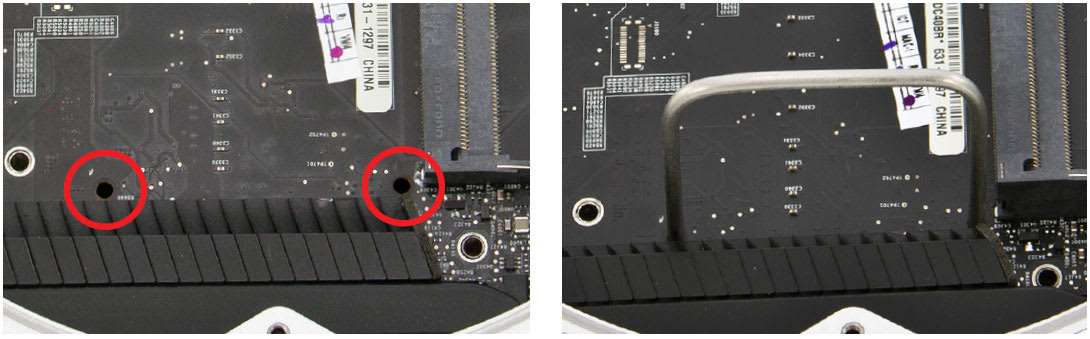
13. Insert the logic board removal tool into the two holes at the bottom of the logic board, as shown in the pictures below. Make sure the tool is securely seated in the holes.
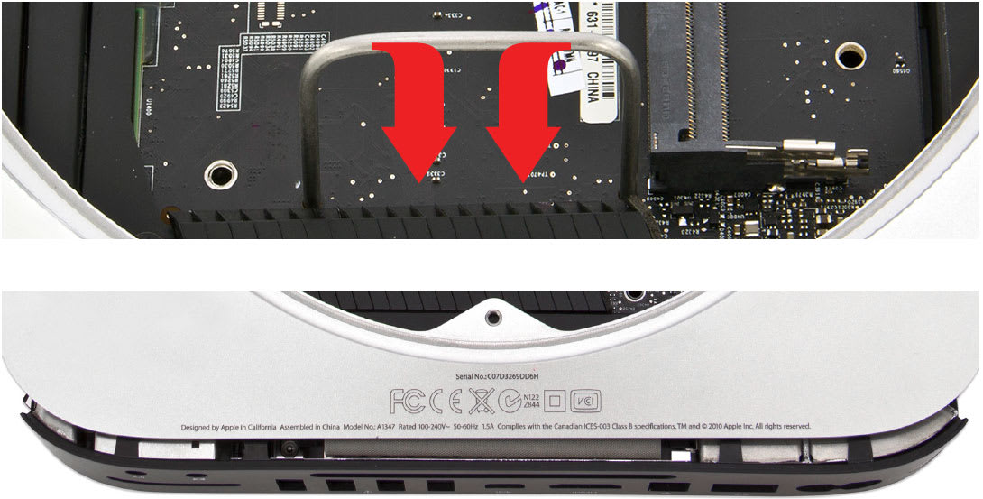
14. Gently push down on the logic board removal tool and pull it back until the black plastic I/O wall pulls away from the aluminum housing slightly, as shown in the pictures below.
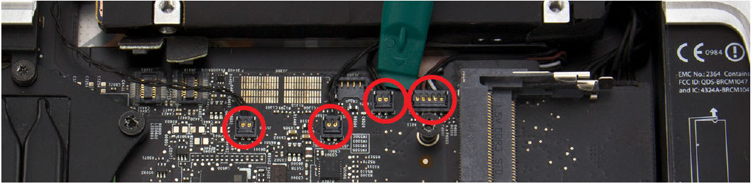
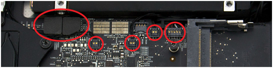
15. Use the nylon pry tool to disconnect the four cables circled in the picture below. Lift the cable connectors straight up; do not pull on the wires.
16. Disconnect the power supply cable, circled in the picture below. Wiggle out the connector with either your fingers or the nylon pry tool. A pair of tweezers may also help.

17. Now that all the cables are disconnected, slide the logic board assembly the rest of the way out of the housing, as shown in the picture below. Be careful to keep the logic board assembly level and avoid catching any of the components on the housing. Be particularly careful when the memory bracket comes out. If the bracket is not level, the bracket clip could catch on the EMI gasket at the top of the housing.
18. To remove the power supply, first remove the T6 screw circled in the picture below.
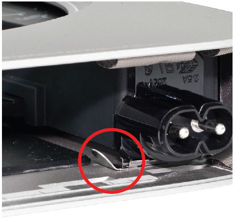
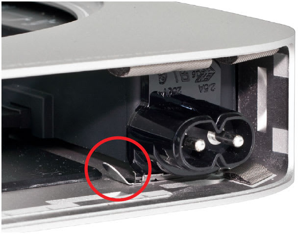
19. Find the metal retention clip holding the power cord socket in place, as circled in the picture below. Slide the retention clip to the left in order to release the power cord socket.
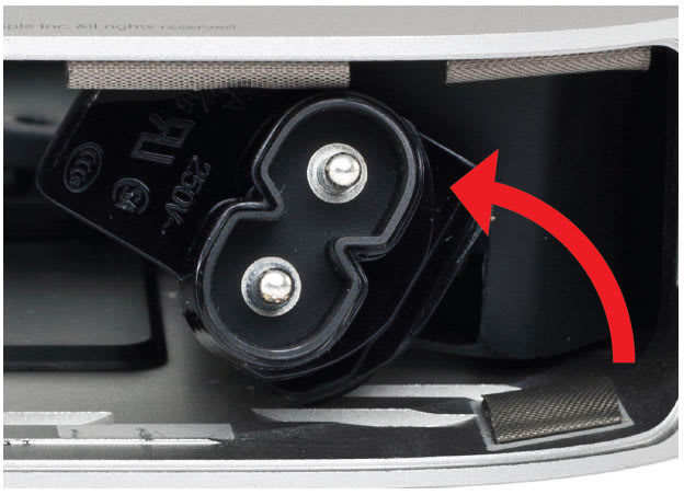
20. Rotate the power cord socket counterclockwise 90° to disengage it from the housing, as shown in the picture below.
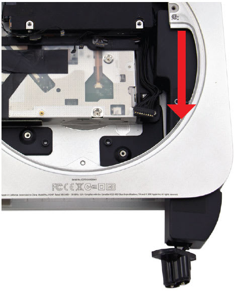
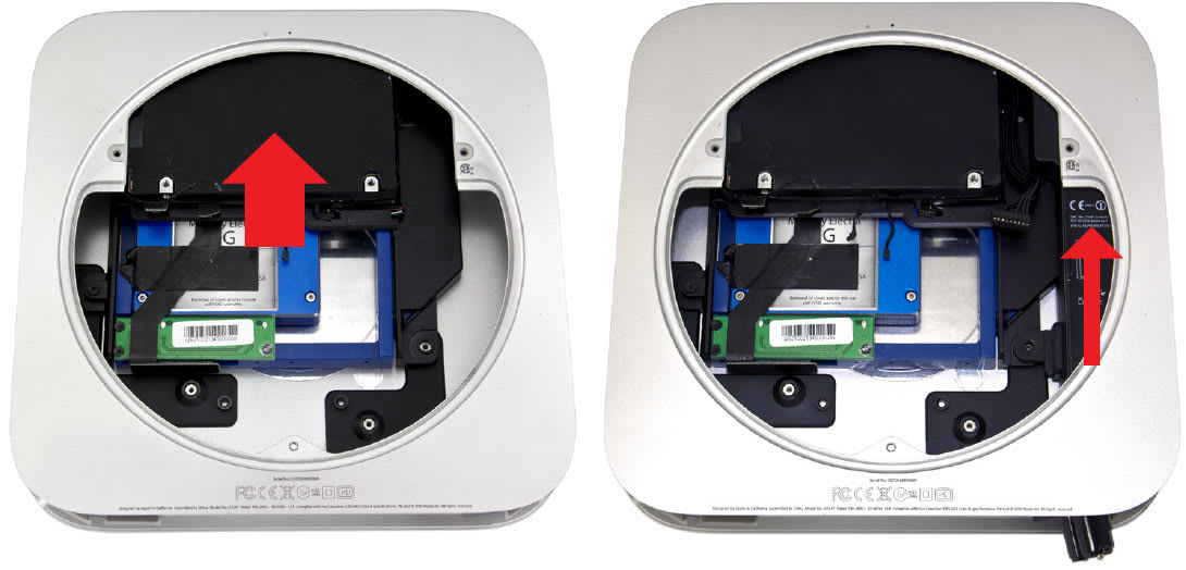
21. Remove the power supply by pulling it straight out of the housing, as shown in the picture below. You may need to rotate the power supply slightly to the left.
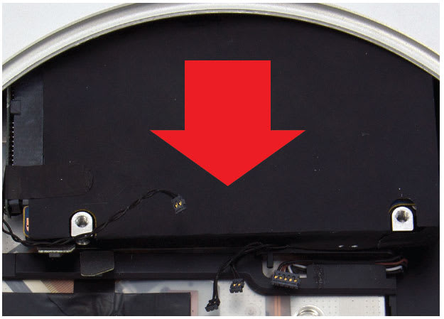
22. Slide the hard drive out of the housing, as shown in the picture below.
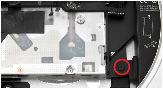
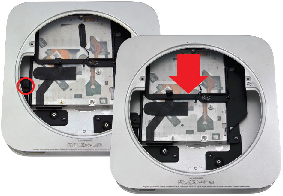
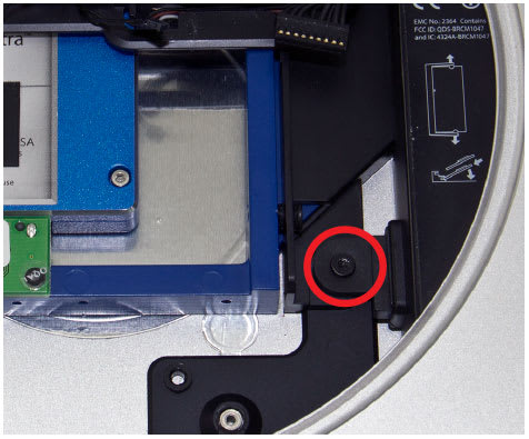
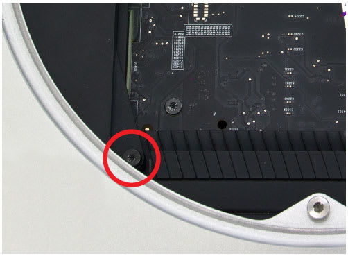
23. Remove the T6 screw securing the optical drive carrier to the housing, as circled in the picture below.
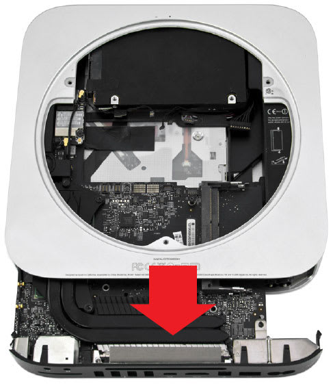
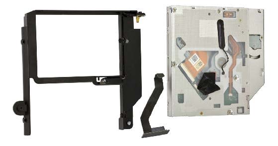
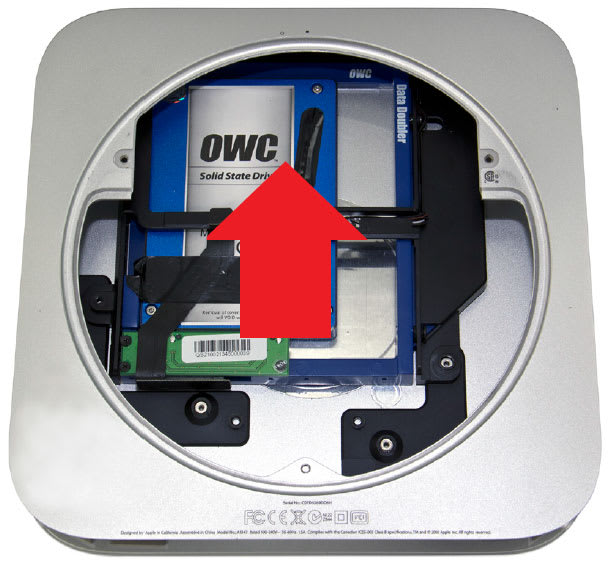
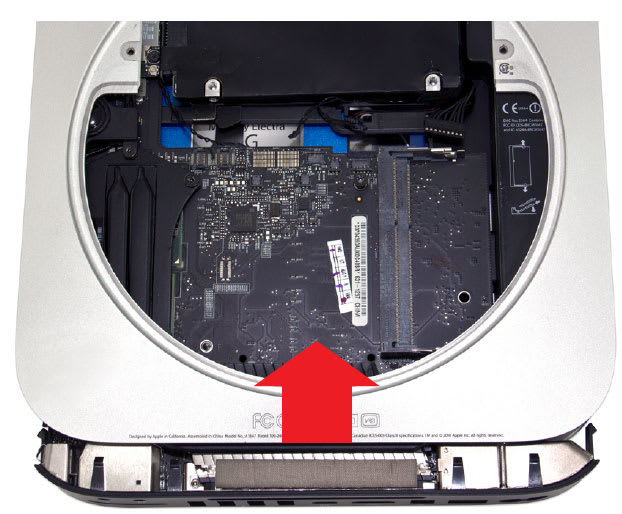
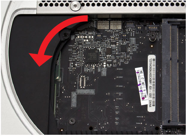
24. Remove the optical drive assembly, including the optical drive and the drive carrier, in the direction indicated by the arrow below.
25. Peel back the tape securing the optical drive flex cable to the optical drive, as shown in the picture below. Be careful, as you will be using this tape again during the installation of the Data Doubler.6.

26. Disconnect the optical drive flex cable from the optical drive, as circled in the picture below. Do not attempt to remove the cable from the assembly. One end of the cable is trapped between the optical drive and the carrier. Simply slide the cable up and out of the way as you go about the process of removing the optical drive.
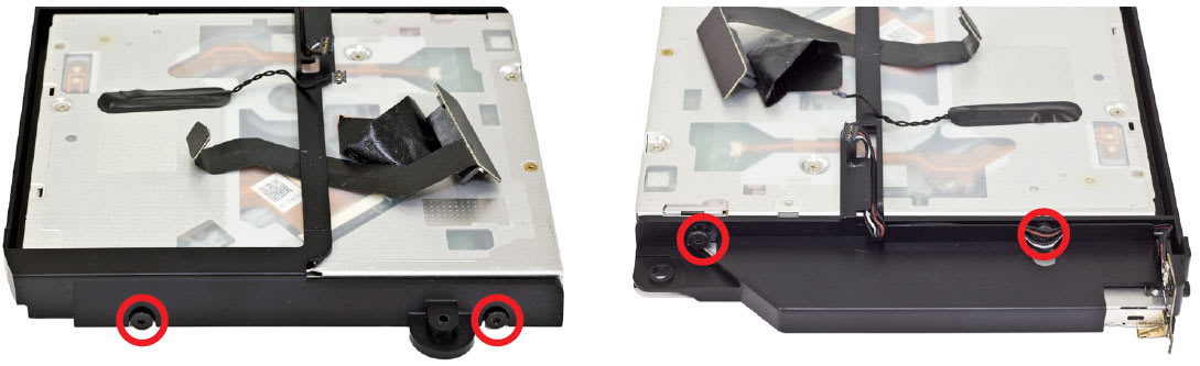
27. Remove the four T8 screws from the optical drive, as circled in the pictures below. These screws are held in place by rubber grommets, so they will remain seated in the carrier once they are removed from the optical drive.
28. Remove the optical drive from the optical drive carrier. At this point, the optical drive flex cable can also be removed.
Disassembly is now complete. Proceed to Section 2.2 Installing the Data Doubler for instructions on installing a drive in the Data Doubler and installing the Data Doubler in the Mac mini.
2.2 Installing the Data Doubler
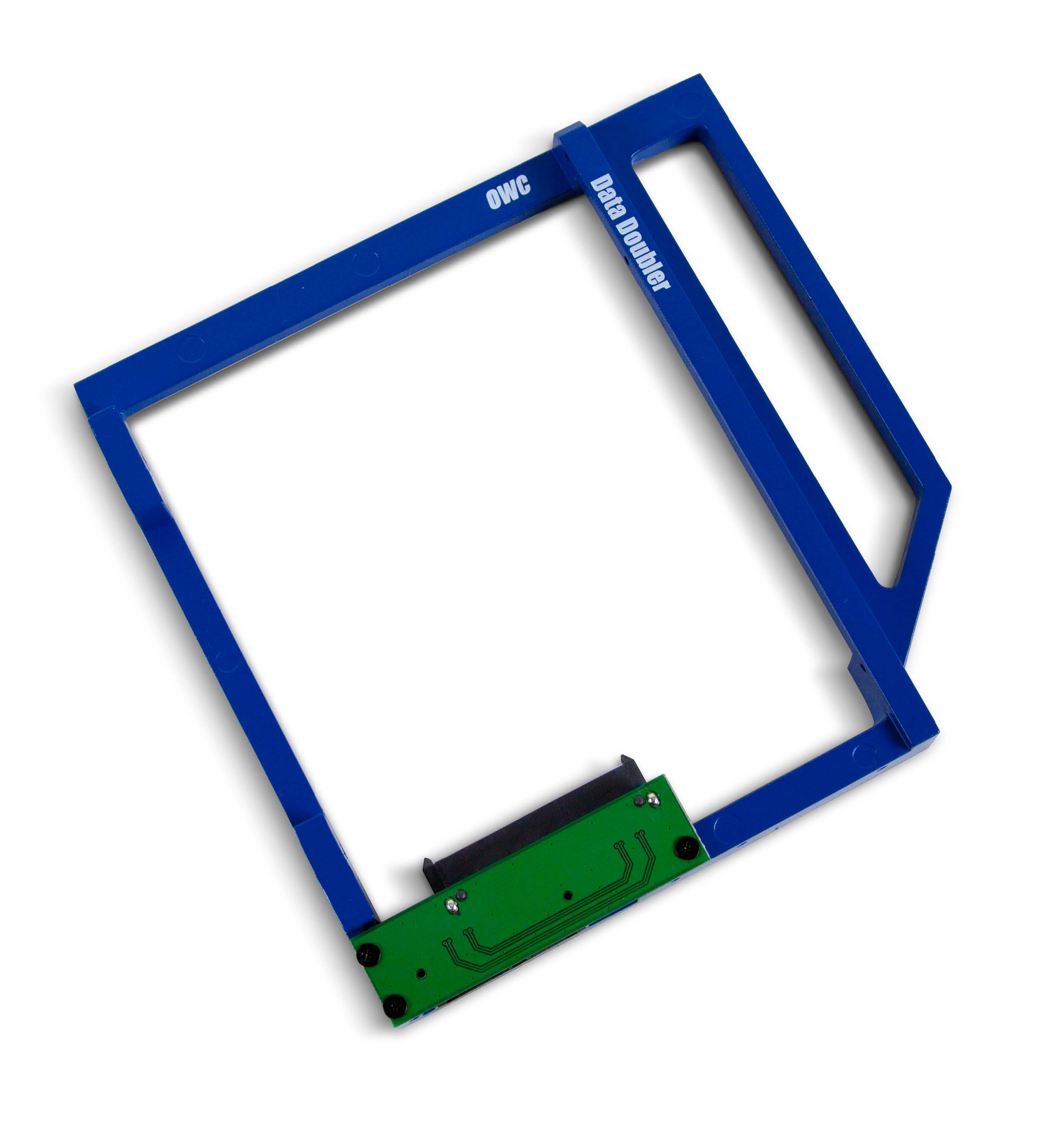
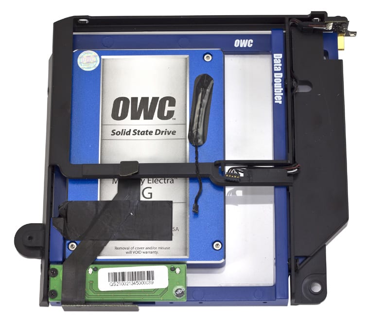
1. Remove the Data Doubler from the box and plastic bag. Note that there is a clear plastic shield on the bottom of the Data Doubler. DO NOT remove this plastic shield. It is a part of the Data Doubler.
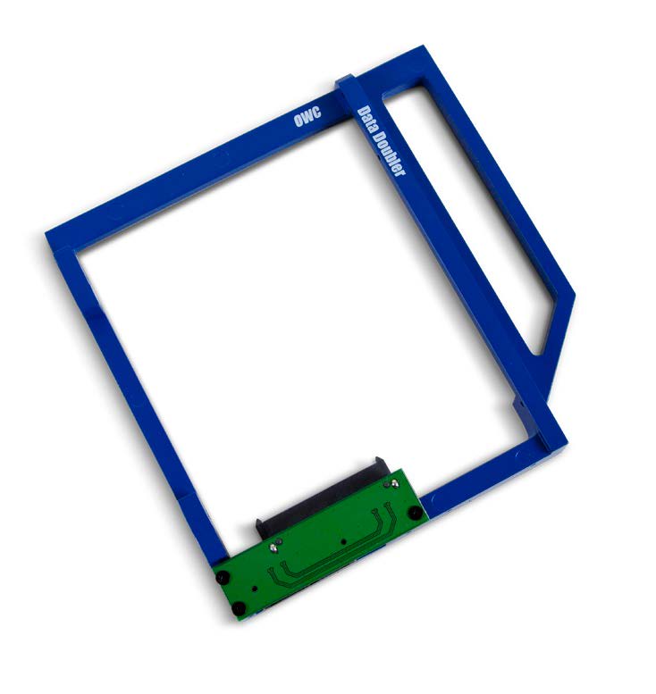
2. Install the 2.5-inch SATA drive into the Data Doubler. Start by sliding the SATA connector on the drive into the black SATA connector attached to the green circuit board on the Data Doubler, as shown below.
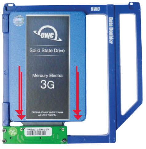
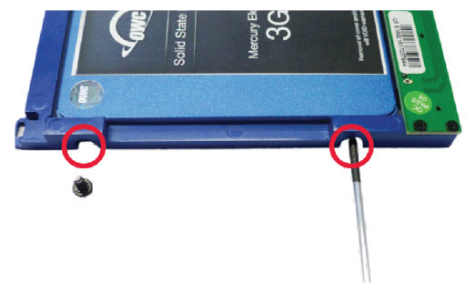
3. Insert the two included Phillips screws into the drive through the screw holes in the Data Doubler, as shown below.
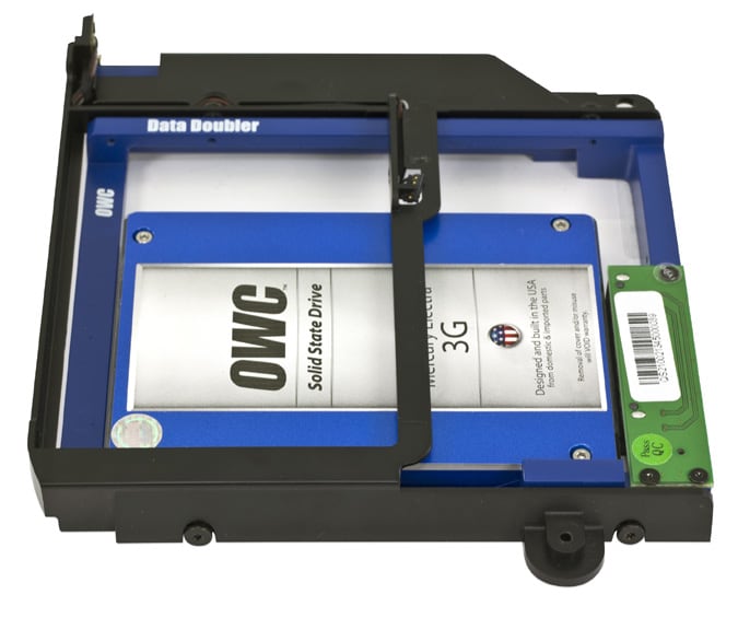
4. Insert the Data Doubler into the optical drive carrier, as shown in the picture below. Note: While the older drive shown in this and subsequent steps is not the same as those shown in Steps 1-3, the process is the same.
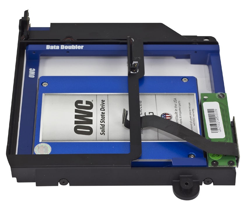
5. Connect the optical drive flex cable to the Data Doubler, as shown in the picture below. There should be enough space between the optical drive carrier and the drive in the data doubler to fit the optical drive flex cable between the two. If you need more space, simply lift up on the optical drive carrier to make room for the cable.
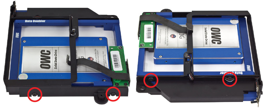
6. Install the four T8 screws, two on each side of the optical drive carrier, as shown in the pictures below.
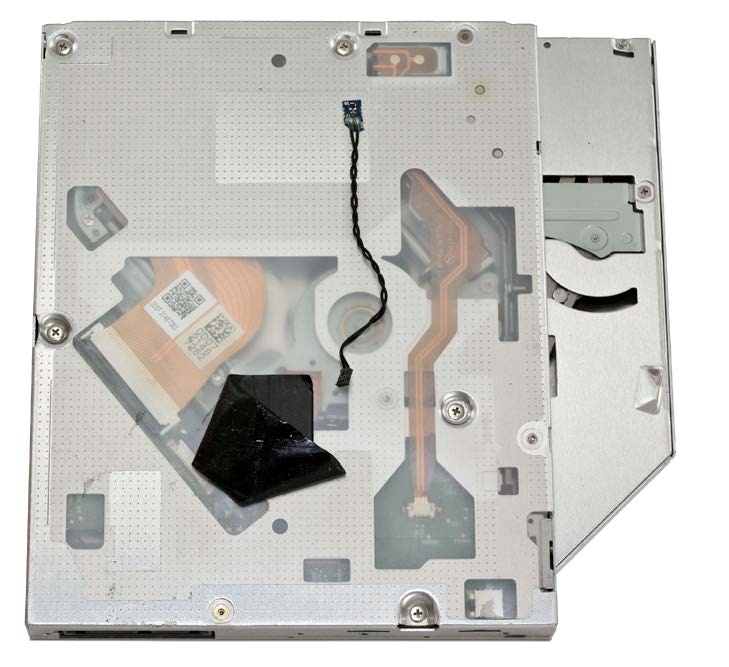
7. Remove the tape attaching the optical drive thermal sensor cable to the optical drive, as shown in the picture below. Be careful, as you will be using this tape again on the Data Doubler.
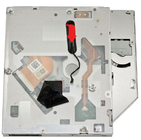
8. Use the nylon pry tool to remove the optical drive thermal sensor cable from the optical drive, as circled in the picture to the left. The cable has some adhesive where it attaches to the optical drive, and the cable can be damaged easily. Note the position of the cable on the optical drive. When you move the cable to the Data Doubler, you want to match the position as closely as possible in order to ensure that there is enough slack to connect the cable back to the logic board.
9. Place the optical drive thermal sensor cable on the drive in the Data Doubler, as shown in the picture below. Remember to align it as closely as possible with the position on the optical drive. Note that the screw just above the cable is in roughly the same position on the optical drive as it is on a hard drive or SSD. Also, the bend in the lower end of the cable should begin just as the cable crosses over the optical drive carrier.
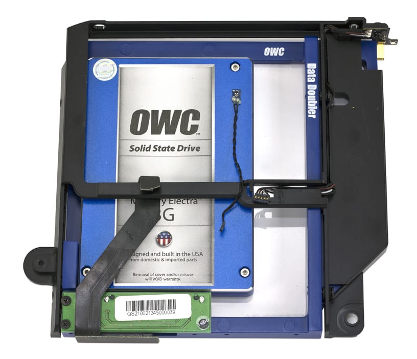
10. Use the original tape to secure the optical drive thermal sensor cable to the drive in the Data Doubler, as shown in the picture below. Also, remove the other piece of tape from the optical drive and use it to secure the optical drive flex cable, as shown in the picture below. The tape will lose some of its adhesive when you remove it from the optical drive, but it will be effective at holding down the cables.
11. Slide the optical drive carrier and Data Doubler assembly into the aluminum housing, as shown in the picture below.

12. Install the T6 screw that secures the optical drive carrier to the housing, as circled in the picture below.
13. Slide the hard drive into the housing, as shown in the picture below. There are two pegs on the hard drive that need to f it into corresponding grommets in the housing.
14. Slide the power supply into the housing, as shown in the picture below. Note that the power supply has two alignment pins, one at the top and one on the right. These pins will fit into their corresponding notches inside the housing.

15. Rotate the power cord socket back to its original position. If you are having difficulty getting the power cord socket to align, it may help to plug in the power cord (make sure the other end is not plugged into an outlet) and use it to straighten out the socket.
16. Slide the metal retention clip back into its groove to hold the power cord socket in place, as circled in the picture below.
17. Install the T6 screw that fastens the power supply to the housing, as circled in the picture below.
18. Slide the logic board most of the way into the housing, as shown in the picture below. Be careful and make sure that all clips and gaskets are entering correctly. The left side of the logic board may bump into the hard drive. If so, simply move the logic board so that it clears the hard drive. Do not slide the logic board all the way in. Leave some space, as shown below.
19. Connect the power supply cable, as circled in the picture below. You can use your fingers, the nylon pry tool, or a pair of tweezers. Make sure none of the other cables are caught or covered by the logic board, then slide the logic board the rest of the way in.

20. Connect the six cables circled in the picture below. Gently push directly down on the cables with your fingers and they will snap into place.
21. Install the T6 screw at the bottom left of the logic board, circled in the picture below.
22. Connect the antenna cable, as circled in the picture below.
23. Move the antenna plate back into place. Note that there is a notch in the housing that the antenna plate needs to fit into in order for the screw holes to align properly. Once the antenna plate is aligned properly, use a Torx T8 screwdriver to install the five screws circled in the picture below. Remember, the screw at the bottom and the two outside screws at the top are 2mm hex screws, but the Torx T8 screwdriver will fit. Be careful not to exert too much force on the hex screws. The two inside screws at the top are standard T8.

24. Install the black plastic cowling, rotating it slightly counter clockwise, as shown in the picture below.
25. Install the short T6 screw at the bottom of the cowling, as circled in the picture below.
26. Connect the fan cable to the logic board, as circled in the picture below.
27. Line up the fan and install the three T6 screws circled in the picture below. The two screws at the top are shorter; the screw at the bottom right is a longer standoff screw.

28. Install the two memory modules according to the instructions circled in the picture below.
29. Install the bottom cover and rotate it clockwise with your thumbs until it locks into place, as shown in the picture below.
The assembly process is now complete. You can now enjoy the use of a second hard drive or solid state drive in your Mac mini.
Support Resources
3.1 Troubleshooting
Begin your troubleshooting by verifying that the power cable is connected to the Mac mini and to a power source. If the power cable is connected to a power strip, make sure that the power switch on the strip is turned on. If the Mac mini will not turn on, or if it is experiencing other problems such as no sound or no wireless connectivity, it is possible that one or more of the internal components were not correctly connected or were damaged during the assembly process. Go back through the assembly instructions and compare what you see with the pictures to identify what is different.
If the drive in the Data Doubler is not seen on the desktop on a Mac, check in the sidebar in a Finder window. Some versions of the Mac operating system do not show hard drives on the desktop by default. If the drive in the Data Doubler is not seen in Finder, check Disk Utility to see if the drive is recognized by the computer. In Windows, check in Disk Management. If the drive is seen there, it may need to be formatted. www.owc.com/format
If problems persist, please contact OWC Support.
3.2 About Data Backup
To ensure that your files are protected and to prevent data loss, we strongly suggest that you keep two copies of your data: one copy on your Data Doubler drive and a second copy on either your primary internal drive or another storage medium, such as an optical backup, or on another external storage unit. Any data loss or corruption while using the Data Doubler is the sole responsibility of the user, and under no circumstances may OWC, its parents, partners, and affiliates be held liable for loss of the use of data including compensation of any kind or recovery of the data.
Changes
The material in this document is for information purposes only and subject to change without notice. While reasonable efforts have been made in the preparation of this document to assure its accuracy, OWC, its parent, affiliates, officers, employees, and agents assume no liability resulting from errors or omissions in this document, or from the use of the information contained herein. OWC reserves the right to make changes or revisions in the product design or the product manual without reservation and without obligation to notify any person of such revisions and changes.
FCC Statement
Warning! Modifications not authorized by the manufacturer may void the user’s authority to operate this device. NOTE: This equipment has been tested and found to comply with the limits for a Class A digital device, pursuant to Part 15 of the FCC Rules. These limits are designed to provide reasonable protection against harmful interference when the equipment is operated in a commercial environment. This equipment generates, uses, and can radiate radio frequency energy and, if not installed and used in accordance with the instruction manual, may cause harmful interference with radio communications. Operation of this equipment in a residential area is likely to cause harmful interference, in which case the user will be required to correct the interference at his own expense.
NOTE: This equipment has been tested and found to comply with the limits for a Class B digital device, pursuant to Part 15 of the FCC Rules. These limits are designed to provide reasonable protection against harmful interference in a residential installation. This equipment generates, uses and can radiate radio frequency energy and, if not installed and used in accordance with the instructions, may cause harmful interference to radio communications. However, there is no guarantee that interference will not occur in a particular installation. If this equipment does cause harmful interference with radio or television reception, which can be determined by turning the equipment off and on, the user is encouraged to try to correct the interference by one or more of the following measures:
- Reorient or relocate the receiving antenna.
- Increase the separation between the equipment and receiver.
- Connect the equipment to an outlet on a circuit different from that to which the receiver is connected.
Health And Safety Precautions
- Read this guide carefully and follow the correct procedures when setting up the device.
- Use proper anti-static precautions while performing the installation for this product. Failure to do so can cause damage to the product, drives, or the computer.
- Do not attempt to disassemble or modify the device. To avoid any risk of electrical shock, fire, short circuiting or dangerous emissions, never insert any metallic object into the device. If it appears to be malfunctioning, please contact OWC Support.
- Never expose your device to rain, or use it near water or in damp or wet conditions. Never place objects containing liquids on the drive, as they may spill into its openings. Doing so increases the risk of electrical shock, short-circuiting, fire or personal injury.
General Use Precautions
- To avoid damage, do not expose the device to temperatures outside the range of 5° C to 40° C (41°F to 104° F).
- Always unplug your computer from the electrical outlet if there is a risk of lightning or if it will be unused for an extended period of time. Otherwise, there is an increased risk of electrical shock, short-circuiting or fire.
- Do not use the device near other electrical appliances such as televisions, radios or speakers. Doing so may cause interference which will adversely affect the operation of the other products.
- Do not place the device near sources of magnetic interference, such as computer displays, televisions or speakers. Magnetic interference can affect the operation and stability of hard drives.
- Do not place heavy objects on top of the device.
- Protect your device from excessive exposure to dust during use or storage. Dust can build up inside the device, increasing the risk of damage or malfunction.
- For up-to-date product and warranty information, please visit the product webpage.
Copyrights and Trademarks
No part of this publication may be reproduced, stored in a retrieval system, or transmitted in any form or by any means, electronic, mechanical, photocopying, recording or otherwise, without the prior written consent of OWC.
© 2021 Other World Computing, Inc. All rights reserved. Data Doubler, OWC, and the OWC logo are trademarks of New Concepts Development Corporation, registered in the U.S. and/or other countries. Apple, AirPort, Mac, Mac mini, macOS, and OS X are trademarks of Apple Inc., registered in the U.S. and other countries. Other marks may be the trademark or registered trademark property of their owners.
Free Support Chat
Our free award-winning support team is ready to answer all of your questions. Technical support is available Monday - Friday: 9AM - 6PM. Customer Support & Sales is available Monday - Friday: 8AM - 8PM. Support is unavailable on U.S. Federal holidays. Talk to a human today.