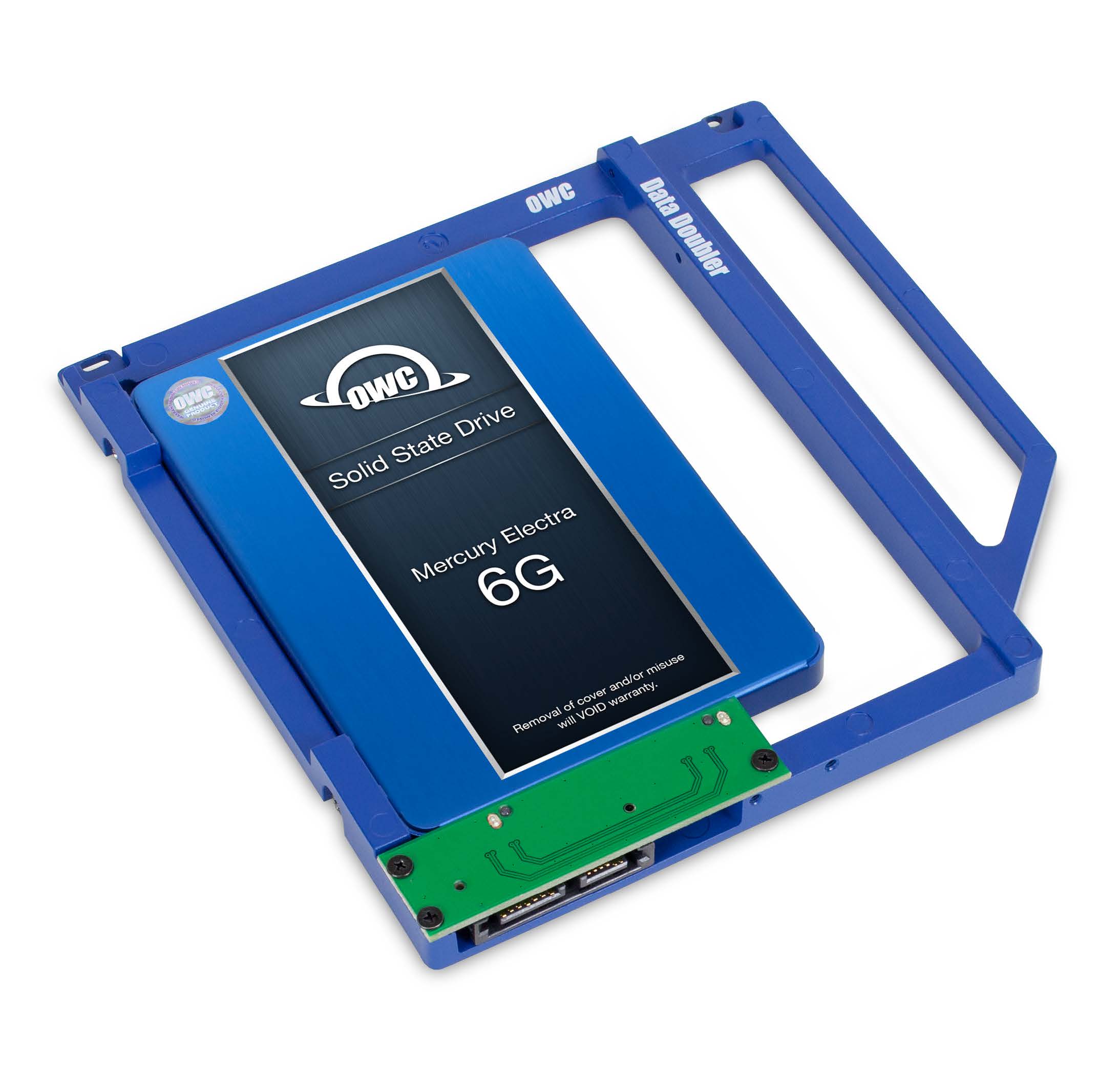
Data Doubler
User Guide
Introduction
1.1 Minimum Requirements
Computer Compatibility
- MacBook 13-inch (Late 2008, Late 2009, Mid 2010)
- MacBook Pro 13-inch (Mid 2009, Mid 2010, Early 2011, Late 2011, Mid 2012)
- MacBook Pro 15-inch (Late 2008, Mid 2009, Mid 2010, Early 2011, Late 2011, Mid 2012)
- MacBook Pro 17-inch (Early 2009, Mid 2009, Early 2010, Early 2011, Late 2011)
Drive Compatibility
- The Data Doubler works with 2.5 inch SATA drives (7mm or 9.5mm drive height)
1.2 Package Contents
- OWC Data Doubler1
- 5-Piece Toolkit
- Installation screws (7)
1.3 About This Manual
The images and descriptions may vary slightly between this manual and the unit shipped. Functions and features may change depending on the firmware version. The latest product details and warranty information can be found on the product web page. OWC’s Limited Warranty is not transferable and subject to limitations.
Attention: Observe Precautions For Handling Electrostatic Sensitive Devices
Your computer is a static-sensitive device. It is susceptible to invisible damage if not protected during installation. We recommend proper grounding by using a grounding strap. Make sure to work in a clean, static-free area, and avoid wearing clothing that retains static charges.
1. Some kits ship with Mercury SSDs.
Installation
2.1 Mounting a 2.5-inch SATA Drive to the Bracket
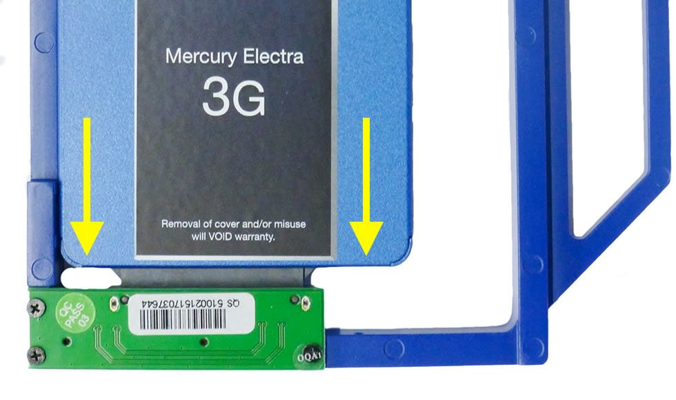
1. Align the drive to the connector on the green circuit board, then apply gentle pressure in the direction shown below to fully connect the drive.
2. Use the two large, round-head Phillips screws from the kit to affix the drive to the side of the Data Doubler bracket (screw hole locations shown in red).
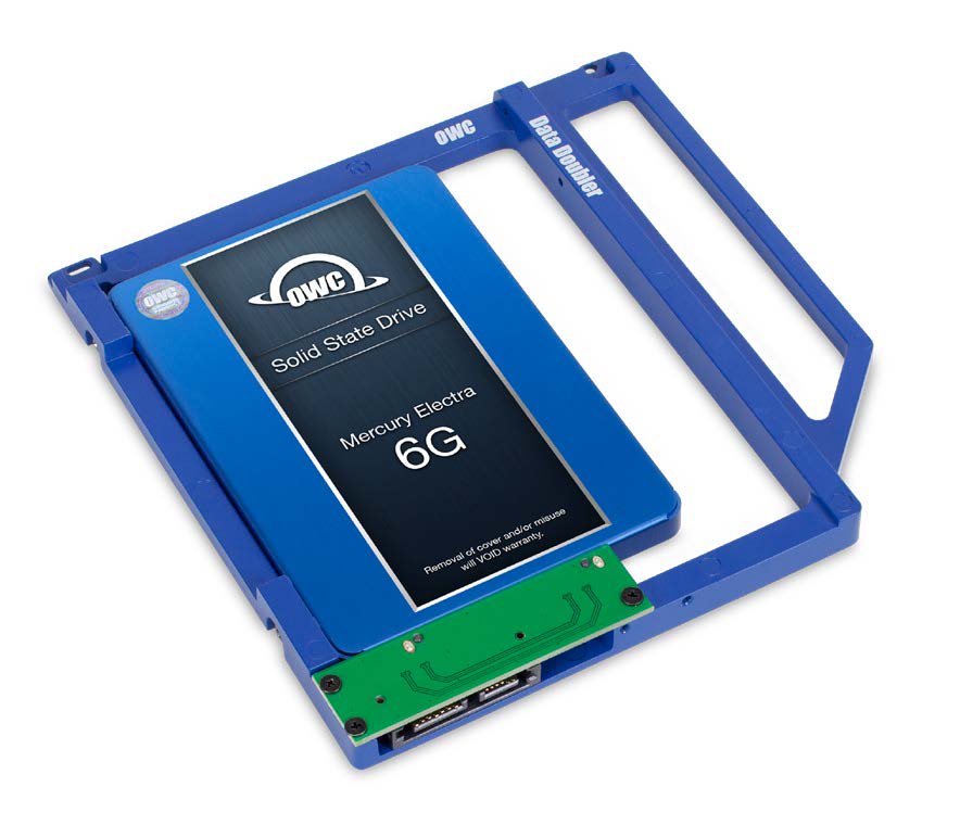
The OWC Data Doubler and SATA drive are now ready for installation.

2.2 Installation by Laptop type
2.2.1 Late 2008 13-inch MacBook (5,1) and Mid-2009 13-inch MacBook Pro (5,5)
Important Note: Before beginning, be sure that your laptop is fully shut down and disconnected from all cables, including the power cable. If you have a MacBook model 5,1, start with Steps 1-3. If you have a MacBook Pro model 5,5 start with Step 4.
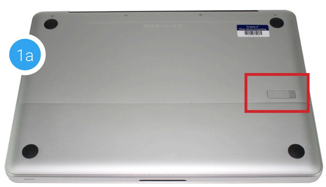
1. Use the release lever (highlighted in 1a in red) to release the battery cover, then remove it (photo, 1b). Recommended: Use the pull-tab on the battery to remove it from the laptop, then set it aside.

2. Next, remove the eight Phillips screws that secure the bottom cover to the chassis.
Note: the three right-most screws along the top edge (shown in yellow) are longer than the rest; install them in the same screw holes at the end of the process. The rest can be used interchangeably in the remaining screw holes.
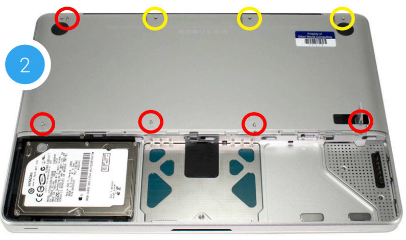
3. Place your fingers on the bottom cover near the black vent opposite the battery compartment, then lift the bottom cover. There are two snap clips holding the cover in place; they will release when you lift the cover. Set the bottom cover aside. You do not need to remove the SATA drive.
Proceed to Step 6.
4. Remove the 10 Phillips screws from the bottom cover. Note: the three right-most screws along the top edge (shown in yellow) are longer than the rest; install them in the same screw holes at the end of the process. The rest can be used interchangeably in the remaining screw holes.
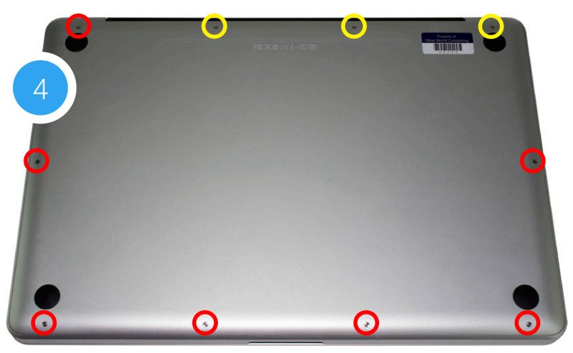
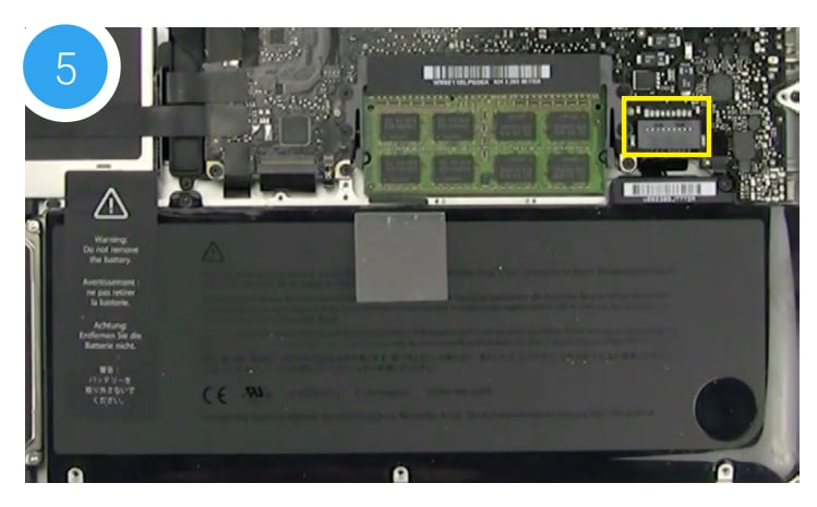
5. Once the screws are removed, place your fingers along the bottom cover near the black vent, then lift the bottom cover. There are two snap clips attached to the cover that will release when you do this. Set the cover aside.
Recommended: before continuing, use the nylon pry tool to gently lift the battery connector (highlighted in yellow) from the logic board.
6. You should see the optical drive (indicated by the red arrow). This drive needs to be removed before you can install the OWC Data Doubler.
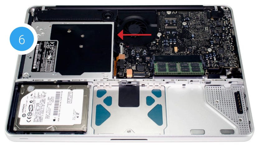
7. Rotate the laptop so the optical drive is oriented in the same manner as the drive shown.
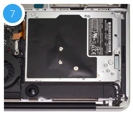
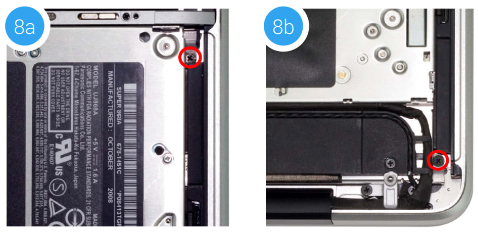
8. Beginning on the right side of the optical drive, remove the two Phillips screws that are highlighted in the photos 8a and 8b.
Note: These screws are not used when reassembling the laptop; store them in a safe place in case you need them later.
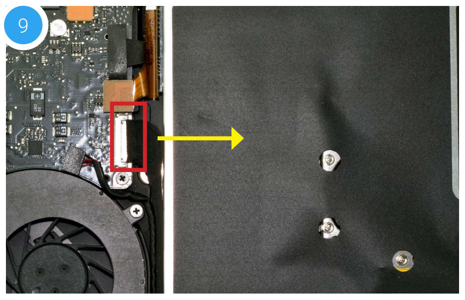
9. Along the left side of the optical drive, between the fan and the orange ribbon cable there is a black cable attached to the logic board. Disconnect the cable by sliding it in the direction shown; this will reveal a screw that was hidden beneath the cable. Caution: this cable is easily damaged.
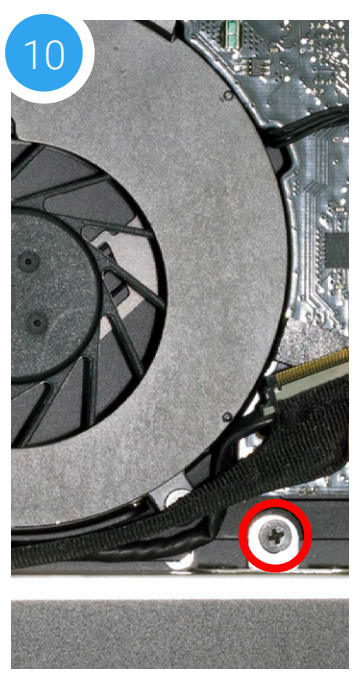
10. Next, remove the Phillips screw that was obscured by the ribbon cable and set it aside; this screw is used during the reassembly process.
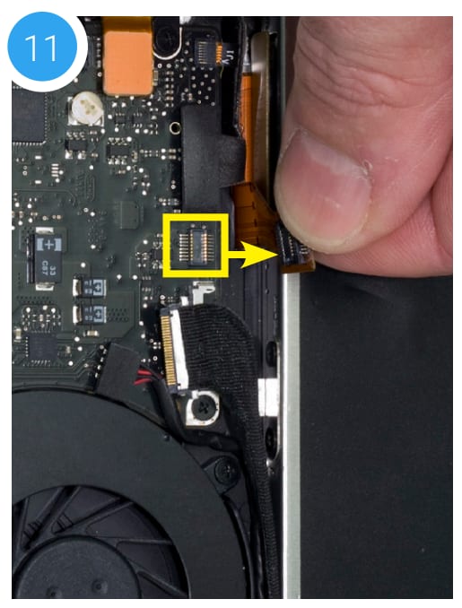
11. Just above the cable that you disconnected in Step 9, there is a ribbon cable — it will be orange or black. This cable is connected to the optical drive. Gently apply upward pressure on the underside of the cable using the included nylon pry tool and disconnect the cable from the logic board.
Caution: this cable is easily damaged.
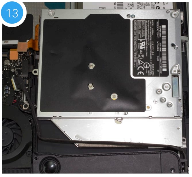
12. There is a speaker housing with an attached wire that is located beneath the optical drive; this housing must be detached from the chassis and set aside before the drive can be removed. Loosen the two Phillips screws that secure the housing (shown below in red) then gently lift it out of the chassis and set it aside. The screws are used during the reassembly process.

13. Carefully lift the edge of the optical drive nearest the orange ribbon cable, then slowly pull the drive out of the optical bay.
Caution: avoid snagging or pulling the cables that were disconnected in earlier steps. They can tear easily if they become caught on the corners of the drive as you lift it out of the chassis.
14. Place the optical drive and the assembled Data Doubler bracket in front of you, as shown below. Note: the cable and optical drive bracket from your laptop may look slightly different.
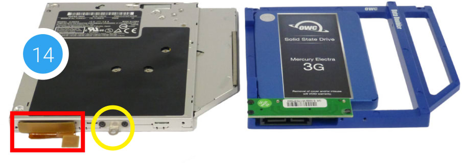
15. To transfer the optical drive cable (see area highlighted in red from the Step 14 photo) to the Data Doubler, first detach it from the drive by gently prying it loose with your fingernail or the nylon pry tool. Then gently pull the cable out of the SATA port.
Caution: this cable is easily damaged.
16. Plug the cable into the Data Doubler’s green circuit board. The location of the installed cable is highlighted in red.
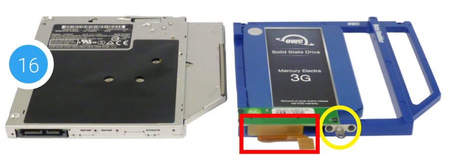
17. Remove the silver bracket that is attached to the back of the optical drive (highlighted in yellow in Step 16) by removing the two Phillips screws. Using the same two screws, affix the silver bracket to the OWC Data Doubler as shown in the photo from Step 16 (highlighted in yellow).
Important: make sure the silver bracket is oriented the same way on the Data Doubler as it was on the optical drive.
18. Carefully place the assembled Data Doubler and attached drive into the optical bay, being careful not to damage any loose cables or connectors.
19. Take the two of the longer Phillips screws included in the Data Doubler Kit and affix them in the same location (shown at right in red) where you removed the two shorter screws in Step 8

20. Carefully reseat the speaker housing and cable from Step 12, then affix the screws you removed that same step. Make sure each screw is affixed in its original location.
21. Affix the screw you removed in Step 10 that secures the optical drive bracket to the laptop chassis.
22. Carefully reconnect the ribbon cable you disconnected in Step 11, then reconnect the cable you disconnected in Step 9.
23. If you disconnected your battery in Step 1 or 5, reconnect it now.
When you’re finished you should see a setup similar to the one shown at right. Note: this photo shows an earlier Data Doubler model with black aluminum.
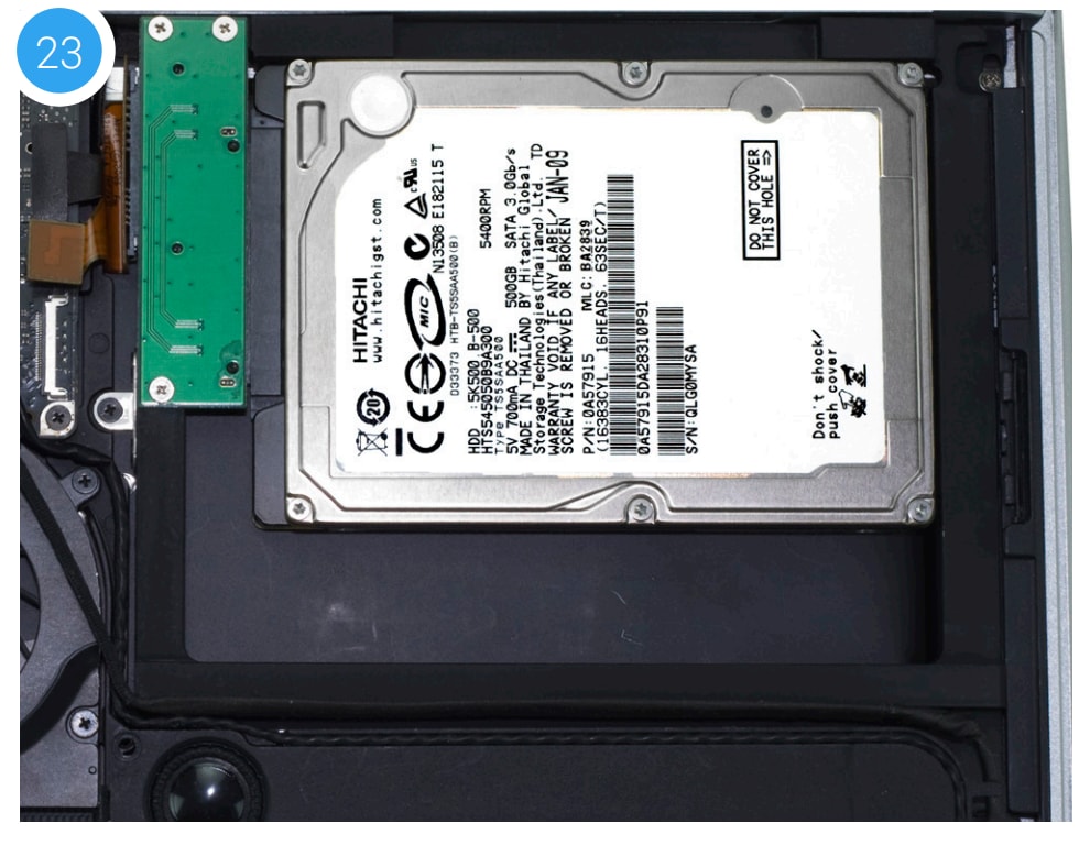
24. Carefully replace the bottom cover, snapping it back into place. If your laptop has a removable battery, affix the eight screws that you removed from the cover in Step 2. If it does not have a removable battery, there will be 10 screws to be affixed (see Step 4). Regardless of battery type, make sure the three long screws are placed in the same screw holes where they were originally installed.
The installation process is complete. Proceed to Section 3.1 Formatting for additional support information.
2.2.2 Late 2009 13-inch MacBook (6,1) and Mid-2010 13-inch MacBook (7,1)
Important: Be sure that your laptop is fully shut down and disconnected from all cables, including the power cable.
1. Remove the eight Phillips screws securing the bottom cover to the chassis.
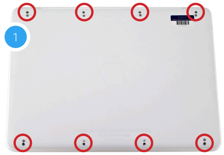
2. Lift the bottom cover from the back of the laptop until the internal clips release the bottom cover. Set the cover and screws aside. The optical drive (indicated by the red arrow) needs to be removed. Recommended: before moving to the next step, use the nylon pry tool to gently lift the battery connector (highlighted in yellow) from the logic board.
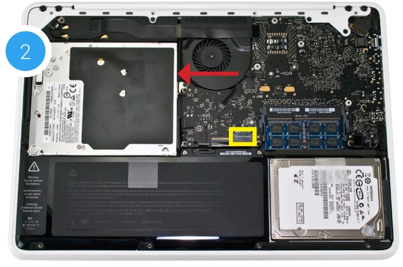
3. Rotate the MacBook around so that the optical drive is oriented as shown below. The rest of the steps in this section assume the same orientation.
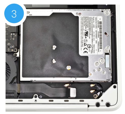
4. Along the left edge of the optical drive, remove the black screw that is used to secure the optical drive bracket to the chassis (shown in red). This screw will be used during the reassembly process.
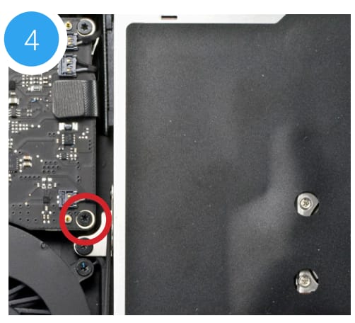
5. Above the screw you removed in Step 4, there is a ribbon cable that connects to the optical drive. It will be either orange or black. Use the nylon pry tool to gently lift the cable's connector, releasing it from the logic board.
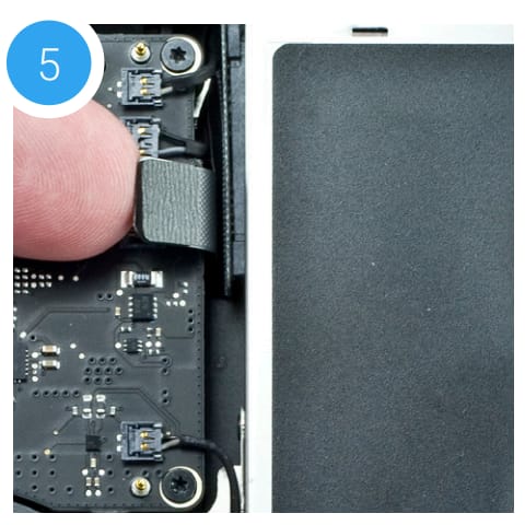
6. Remove the silver screw (highlighted in red) that is located near the top-right corner of the optical drive. It is partially concealed by a black plastic tab that is part of the battery. Note: This screw will not be used during the reassembly process; store it in a safe place in case you need it later.
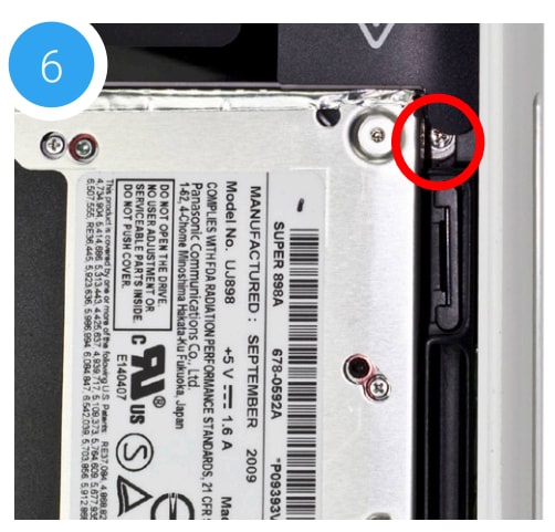
7. Along the bottom-right corner of the chassis, there are four screws that need to be removed (shown in red). The two smaller screws are Phillips screws, the two larger screws are Torx T8. Set the screws aside
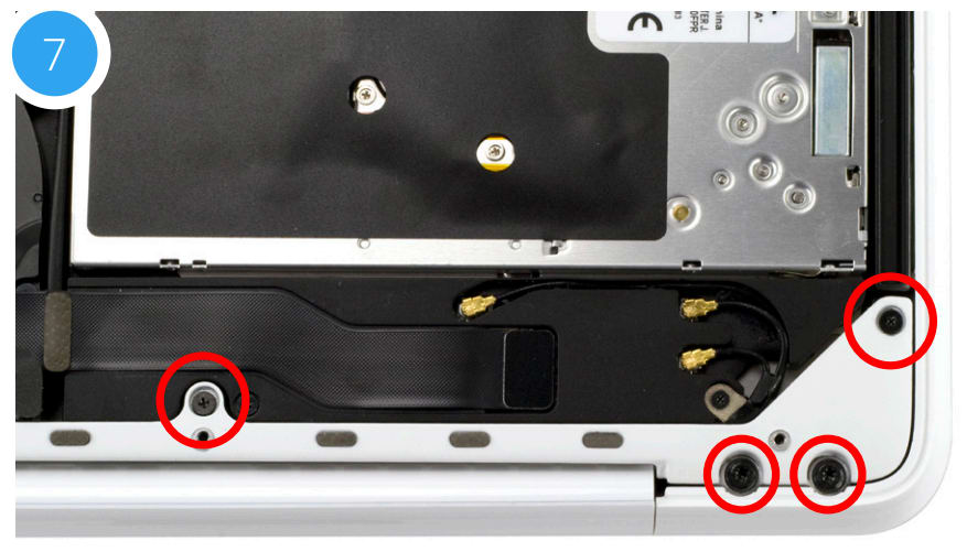
8. Along the bottom-left of the chassis there are four additional screws that need to be removed. Again the two smaller screws are Phillips screws and the two larger screws are Torx T8. Set the screws aside.

9. The screws that were removed in Steps 7 and 8 held the rear vent in place. Lift the rear vent up then remove it and set it aside. The shots below show the rear vent intact (9a) and removed (9b).


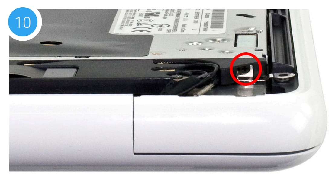
10. On the right side of the optical drive there is a small black Phillips screw (shown in red) that holds a small plastic housing to the optical drive. Remove the screw. This screw will be used during reassembly
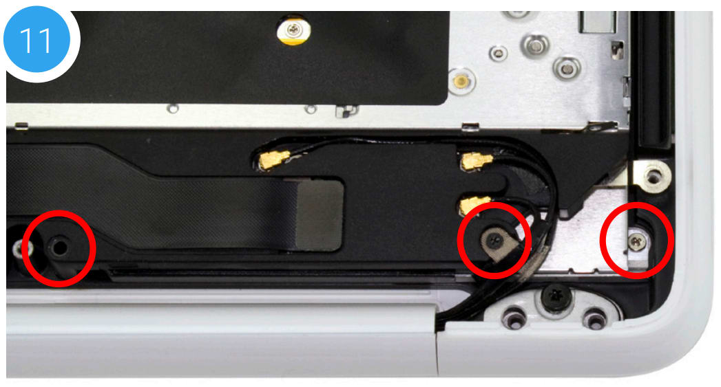
11. Remove the three Phillips screws highlighted below. Note: The short silver screw on the far right will not be reused during reassembly; store it in a safe place in case you need it later. The screw on the far left is longer than the middle screw; each needs to be placed in the same location later.
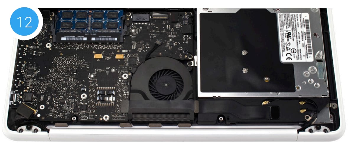
12. Lift up on the optical drive from the area near the ribbon cable and gently remove it from the optical bay
13. Place the optical drive and the assembled Data Doubler bracket in front of you. Note: the cable and optical drive bracket from your laptop may look slightly different.
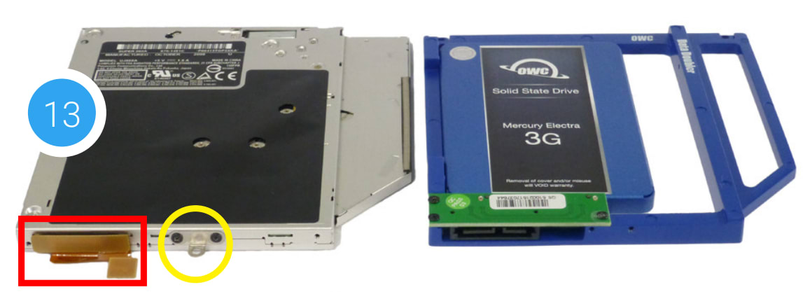
14. To transfer the optical drive cable (see area highlighted in red from Step 13 photo) to the Data Doubler, first detach it from the drive by gently prying it loose with your fingernail or the nylon pry tool. Then gently pull the cable out of the SATA port. Caution: this cable is easily damaged.
15. Plug the cable into the Data Doubler’s green circuit board. The location of the installed cable is highlighted in red.
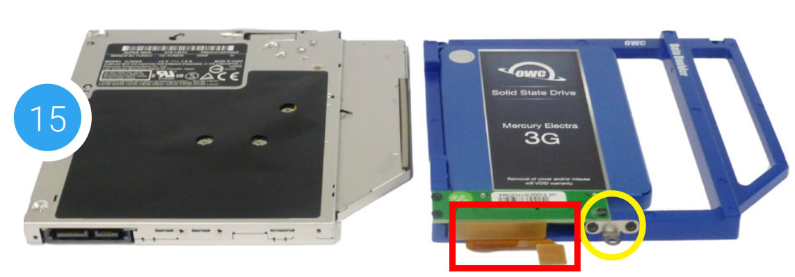
16. Remove the silver bracket that is attached to the back of the optical drive (highlighted in yellow in Step 13) by removing the two Phillips screws. Using the same two screws, affix the silver bracket to the OWC Data Doubler as shown in the photo from Step 15 (highlighted in yellow). Important: make sure the silver bracket is oriented the same way on the Data Doubler as it was on the optical drive.
17. Begin the reassembly process by placing the Data Doubler under the black plastic bracket first, then into the optical bay. Be careful not to damage any of the cables or connectors. Press down on the ribbon cable's connector to secure it to the logic board again. Note: this photo shows an earlier Data Doubler with black aluminum.
18. Affix two of the longer screws from the kit in the locations highlighted in red. Note: the lower screw was removed in Step 11.
19. Affix the two remaining screws you removed in Step 11 at the locations shown in yellow. The longer screw should be placed in the left-most hole.
20. Affix the optical drive bracket screw from Step 4, at the location highlighted in blue. Next, affix the screw you removed in Step 10.

21. Reattach the rear vent to the laptop. Make sure the venter is flush with the chassis (21b).


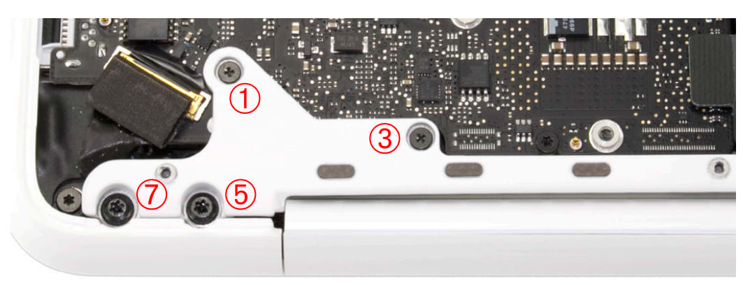
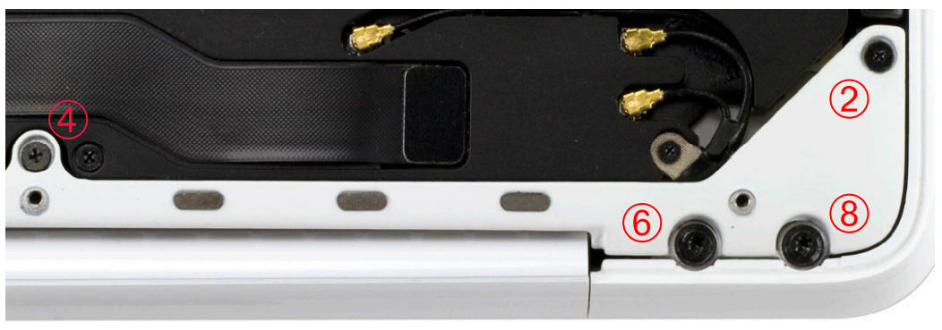
22. Reinsert the four Phillips screws that were removed from the rear vent in the order shown below (1-4). Initially, tighten them just enough to get the screws threaded. Then, tighten all four firmly.
23. Reinsert the four Torx T8 screws into the rear vent and as in the previous step, tighten them just enough to get them threaded (5-8). Then tighten all four firmly. If you disconnected your battery in Step 2, reconnect it now.
24. Reattach the bottom cover to the chassis and affix the eight Phillips screws that were removed in Step 1. The installation process is complete. Proceed to Section 3.1 Formatting for additional support information.
2.2.3 Mid-2010 13-inch MacBook Pro (7,1)
Important: Be sure that your laptop is fully shut down and disconnected from all cables, including the power cable.
1. Remove the 10 Phillips screws that secure the bottom cover to the chassis.
Note: the three right-most screws along the top edge (shown in yellow) are longer than the rest; install them in the same screw holes at the end of the process. The rest can be used interchangeably in the remaining screw holes.
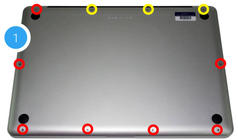
2. Once the screws are removed, place your fingers on the bottom cover near the black vent, then lift the cover. There are two snap clips attached to the cover that will release when you do this. Set the cover aside. Continue to the next step.
3. You should see the optical drive (indicated with red arrow). This drive needs to be removed before you can install the OWC Data Doubler. Recommended: before moving to the next step, use the nylon pry tool to gently lift the battery connector (highlighted in yellow) from the logic board.
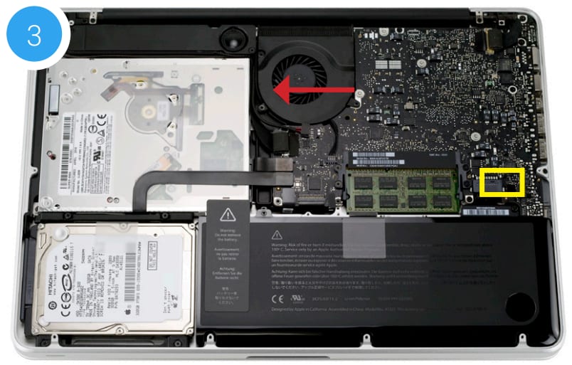
4. Rotate the laptop so the optical drive is oriented in the same manner as the drive shown.
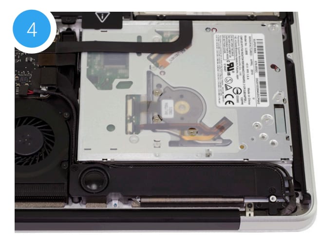
5. Beginning on the right side of the optical drive, remove the two Phillips screws that are highlighted in the photos 5a and 5b. Note: the two screws removed in this step will not be used when reassembling the laptop; store them in a safe place in case you need them later.

6. Locate the two black ribbon cables to the left of the optical drive, which are connected to the logic board. They are about halfway between the fan and the battery (highlighted in red).
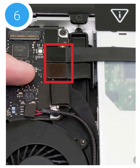
7. Gently lift each cable using the nylon pry tool, in order to disconnect each one from the logic board.
Caution: these cables are easily damaged.

8. Locate the metal bracket that is attached to the left edge of the optical drive with a small Phillips screw. It is just above the fan and below the cables you disconnected in Step 7.
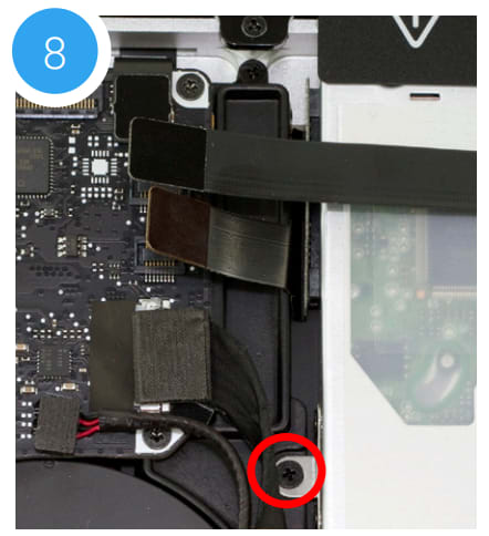
9. Remove the Phillips screw, being careful to not damage the small cable that sits between the logic board and the optical drive. This screw will be used again later during reassembly.
10. There is a speaker housing with an attached wire that is located beneath the optical drive; the housing must be detached and moved aside before the drive can be removed. Loosen the two Phillips screws that secure the housing (shown in red) and gently lift it out of the chassis. You do not need to detach it completely. These screws will be used during reassembly.
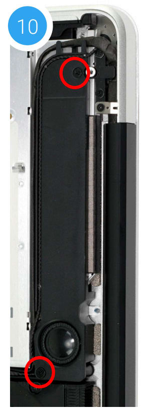
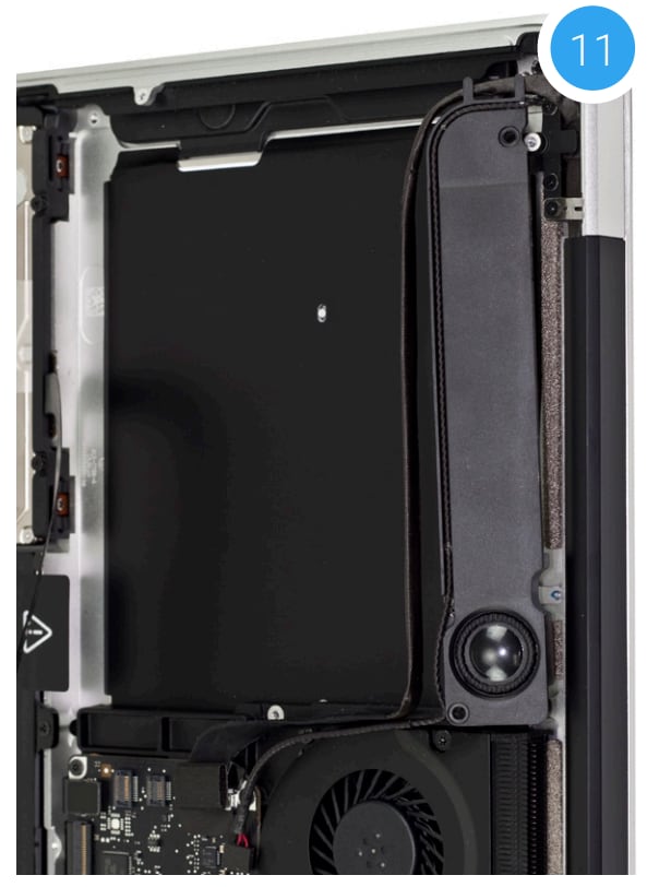
11. Carefully lift the edge of the optical drive nearest the ribbon cables, then slowly pull the drive out of the optical bay. The empty bay is shown.
Caution: avoid snagging or pulling the cables that were disconnected in earlier steps. They can tear easily if they catch on the corners of the drive as you lift it out of the chassis.
12. Place the optical drive and the assembled Data Doubler bracket in front of you, as shown below. Note: the cable and optical drive bracket from your laptop may look slightly different.
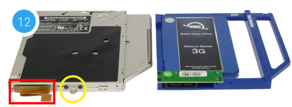
13. To transfer the optical drive cable (see area highlighted in red in Step 12 photo) to the Data Doubler, first detach it from the drive by gently prying it loose with your fingernail or the nylon pry tool. Then gently pull the cable out of the SATA port. Caution: this cable is easily damaged.
14. Plug the cable into the Data Doubler’s green circuit board. The location of the installed cable is highlighted in red.
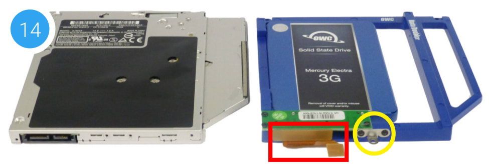
15. Remove the silver bracket that is attached to the back of the optical drive (highlighted in yellow in Step 12) by removing the two Phillips screws. Using the same two screws, affix the silver bracket to the OWC Data Doubler as shown in the photo from Step 14 (highlighted in yellow). Important: make sure the silver bracket is oriented the same way on the Data Doubler as it was on the optical drive.
16. Carefully place the assembled Data Doubler bracket into the optical bay, being careful not to damage any cables or connectors. Make sure the battery tab is resting atop the seated bracket. Note: this photo shows an earlier Data Doubler model with black aluminum.
17. Reseat the speaker housing and cable from Step 10 then affix the screws in their original locations. Next Affix the screw you removed in Step 8.

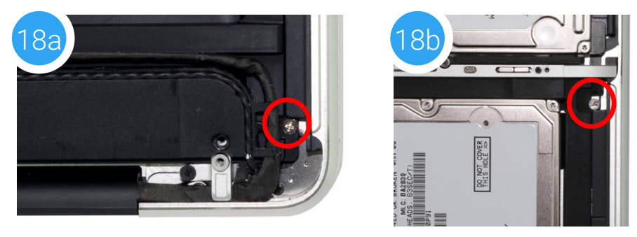
18. Take two longer Phillips screws from the Data Doubler Kit and affix them in the locations shown in photos 18a and 18b (the original screws were removed in Step 5).
19. Re-connect the two ribbon cables from Step 7. If you disconnected your battery in Step 3, reconnect it now.
20. Carefully replace the bottom cover, snapping it back into place. Affix the 10 Phillips screws that were removed in Step 1; make sure the three longest screws are inserted in their original locations.
The installation process is complete. Proceed to Section 3.1 Formatting for additional support information.
2.2.4 Early/Late 2011 13-inch MacBook Pro (8,1) and Mid-2012 13-inch MacBook Pro (9,2)
Important: Be sure that your laptop is fully shut down and disconnected from all cables, including the power cable.
1. Remove the 10 Phillips screws that secure the bottom cover to the chassis.
Note: the three right-most screws along the top edge (shown in yellow) are longer than the rest; install them in the same screw holes at the end of the process. The rest can be used interchangeably in the remaining screw holes.
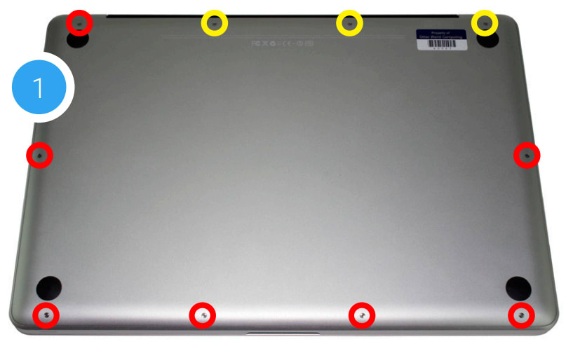
2. Once the screws are removed, place your fingers on the bottom cover near the black vent, then lift the cover. There are two snap clips attached to the cover that will release when you do this. Set the cover aside.
3. You should see the optical drive (indicated with arrow). This drive needs to be removed before you can install the OWC Data Doubler. Recommended: before moving to the next step, use the nylon pry tool to gently lift the battery connector (highlighted in yellow) from the logic board.
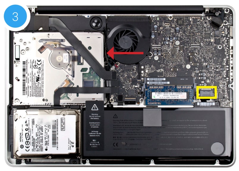
4. Rotate the laptop so the optical drive is oriented in the same manner as the drive shown in image.
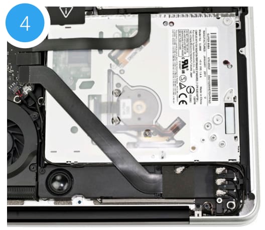
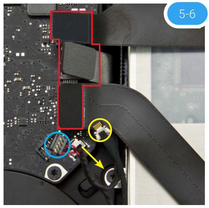
5. Follow the two black ribbon cables that sit atop the optical drive to their connection points on the logic board. There is also a third ribbon cable connector between them. All are highlighted in red. Carefully disconnect all three using the nylon pry tool.
6. Between the ribbon cables that were disconnected in Step 5 and the fan, there are two additional cables — one black cable with two red wires (highlighted in blue) and another black cable with a silver connector (highlighted in yellow). For the latter, carefully pull the cable towards the optical drive, in the direction shown. For the connector highlighted in blue, use the nylon pry tool to gently lift the corner of the connector from the logic board (try lifting the corner nearest the screw). Caution: the cables shown in this step are damaged easily.
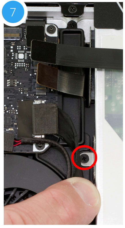
7. Near the left edge of the optical drive, between the fan and the ribbon cables there is a metal bracket that is attached to the optical drive with a small Phillips screw (highlighted in red). Remove the screw; be careful to not damage the cable that is between the logic board and the optical drive. This screw will be used again during the reassembly process.
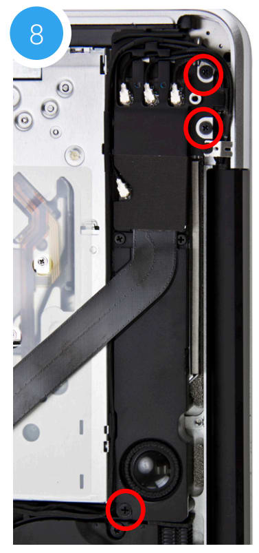
8. Next to the optical drive there is a speaker housing that is held in place by three Phillips screws; remove them. Once the screws are removed, gently lift up on the speaker housing to dislodge it from its mounting posts. The speaker’s cable should remain connected. The left-most screw is shorter than the other two and will need to be affixed in the same location later. All three screws will be used again during the reassembly process.
9. Gently lift the speaker housing up and away from the corner of the chassis. This will expose a Phillips screw near the corner that secures the optical drive to the chassis (shown in red). Remove the screw and store it in a safe location; it will not be used during the reassembly process.
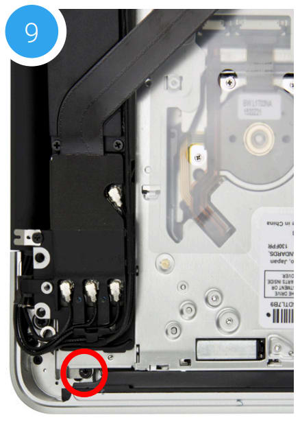
10. There is a second Phillips screw that secures the optical drive to the chassis (along the same edge of the drive and on the opposite end as the screw removed in Step 9). Remove this screw and store it in a safe location; it will not be used during the reassembly process
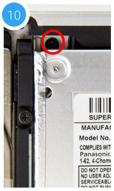
11. Gently lift the optical drive out of the drive bay, being careful to not damage any cables in the process. Note: the orientation of this photo shows the corner of the chassis nearest the optical drive at the top of the photo.
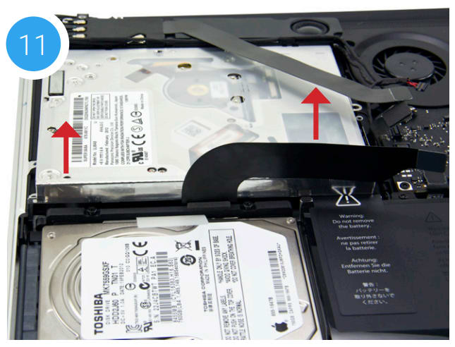
12. Place the optical drive and the assembled Data Doubler bracket in front of you, as shown. Note: the cable and optical drive bracket from your laptop may look slightly different.
13. To transfer the optical drive cable (highlighted in red in Step 12) to the Data Doubler, first detach it from the drive by gently prying it loose with your fingernail or the nylon pry tool. Then gently pull the cable out of the SATA port. Caution: this cable is easily damaged.
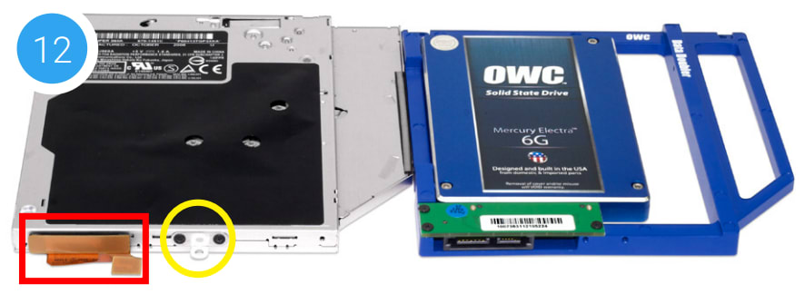
14. Plug the cable into the Data Doubler’s green circuit board. The location of the installed cable is highlighted in red below.

15. Remove the silver bracket that is attached to the back of the optical drive (highlighted in yellow in Step 12) by removing the two Phillips screws. Using the same two screws, affix the silver bracket to the OWC Data Doubler as shown in the photo from Step 14 (highlighted in yellow). Important: make sure the silver bracket is oriented the same way on the Data Doubler as it was on the optical drive.
16. Carefully place the assembled Data Doubler and attached drive into the optical bay, being careful not to damage any cables or connectors. Next, take two longer Phillips screws from the Kit and affix them in the same location where you removed two shorter screws in Steps 9 and 10.
17. Next, affix the screws that you removed in Step 7 to the bracket you attached to the Data Doubler in Step 14 (shown below in yellow).
18. Reseat the speaker housing and cable from Step 8 then affix the screws you removed in that step (shown in red). Note: the longer screw must go into the leftmost screw hole on the housing.
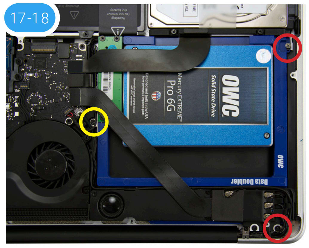
19. Carefully re-insert the cable connectors you disconnected in Step 6, then reconnect the ribbon cables you disconnected in Step 5. If you disconnected your battery in Step 3, reconnect it now.
20. Carefully reseat the bottom cover, snapping it back into place. Affix the 10 Phillips screws that were removed in Step 1; make sure the three long screws are placed in their original locations.
The installation process is complete. Proceed to Section 3.1 Formatting for additional support information.
2.2.5 Late 2008 15-inch MacBook Pro (5,1) and Mid-2009 15-inch MacBook Pro (5,3 and 5,4)
Important: Be sure that your laptop is fully shut down and disconnected from all cables, including the power cable. If you have a MacBook Pro model 5,1 start with Steps 1-3. If you have a MacBook Pro model 5,3 or 5,4, skip ahead to Step 4.
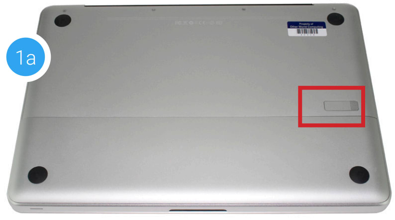
1. Use the release lever (highlighted in red) to release the battery cover, then remove it (bottom photo). Recommended: Use the pull-tab on the battery to remove it from the laptop, then set it aside.
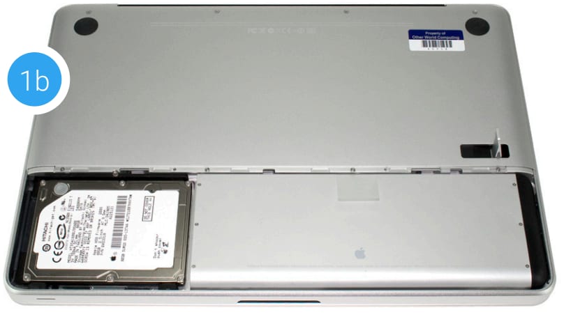
2. Use the pull-tab on the battery to remove it from the laptop, then set it aside. Next, remove the eight Phillips screws that secure the bottom cover to the chassis (highlighted below).
Note: The three right-most screws along the top edge (shown in yellow) are longer than the rest; install them in the same screw holes at the end of the process. The rest can be used interchangeably in the remaining screw holes.
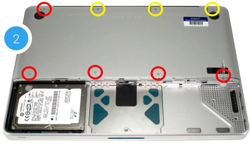
3. Once the screws are removed, place your fingers on the bottom cover, near the black vent opposite the battery compartment, then lift the bottom cover. There are two snap clips holding the cover in place; they will release when you lift the cover. Set the bottom cover aside. You do not need to remove the SATA drive.
Proceed to Step 5.
4. Remove the 10 Phillips screws that secure the bottom cover to the chassis.
Note: The three right-most screws along the top edge (shown in yellow) are longer than the rest; install them in the same screw holes at the end of the process. The rest can be used interchangeably in the remaining screw holes.
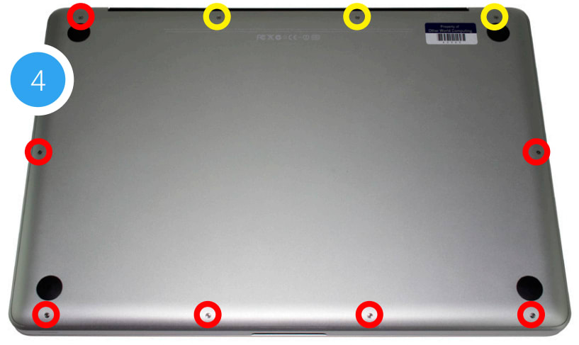
5. Once the screws are removed, place your fingers along the bottom cover near the black vent, then lift the bottom cover. There are two snap clips attached to the cover that will release when you do this. Set the cover aside.
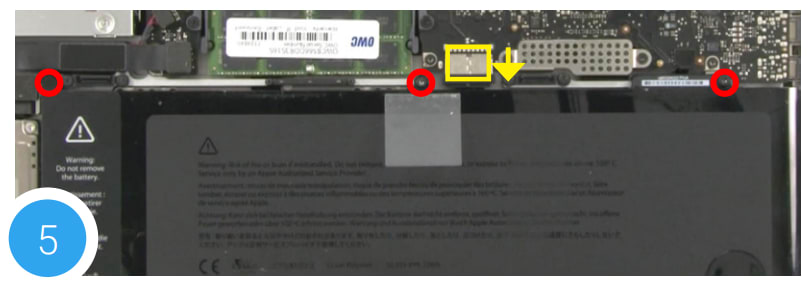
Recommended: before moving to the next step, use a Torx T6 driver to remove the three battery screws shown below in red, then pull the battery tab so the battery stands up in the bay. Next use the nylon pry tool to gently push the connector towards the battery bay and out of its slot
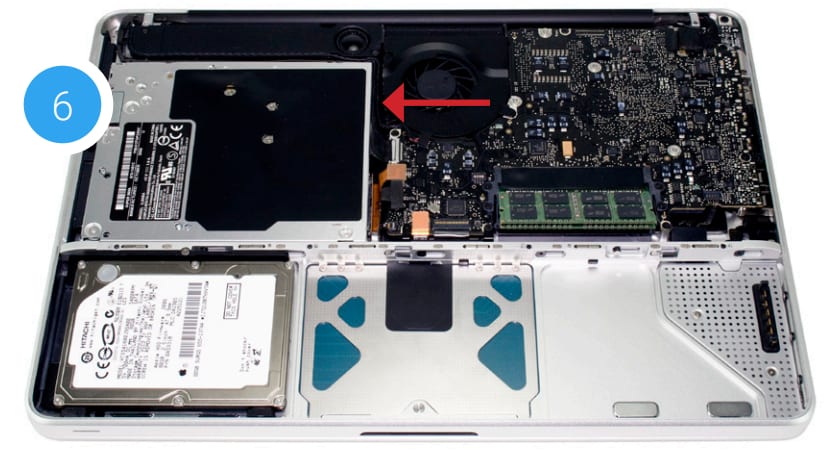
6. You should see the optical drive (indicated with arrow). This drive needs to be removed before you can install the OWC Data Doubler.
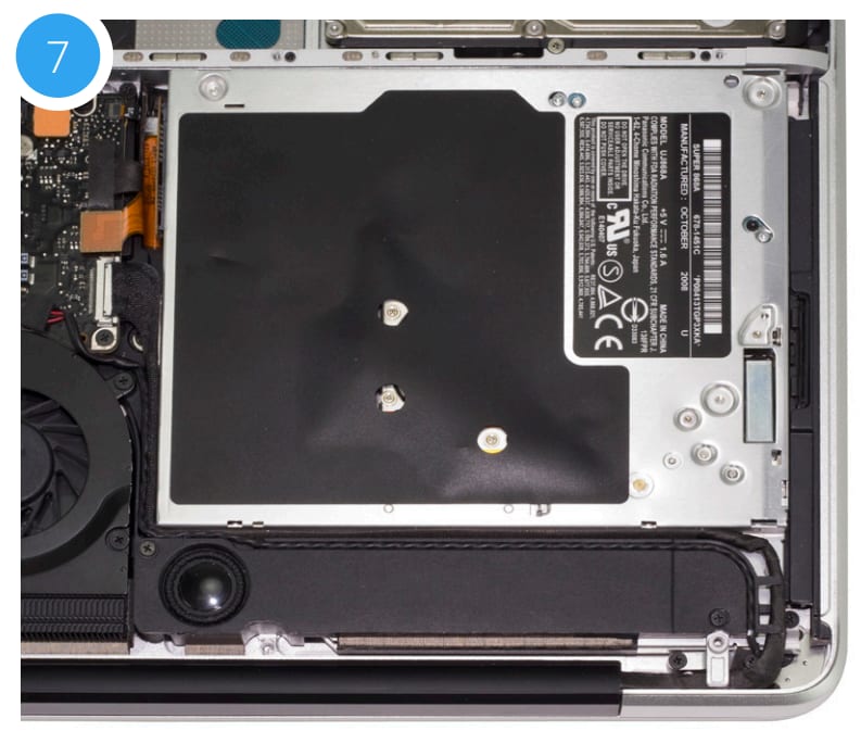
7. Rotate the laptop so the optical drive is oriented in the same manner as the drive shown below.
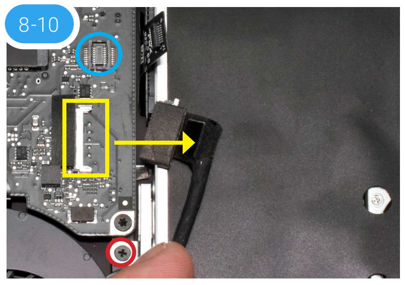
8. Near the left edge of the optical drive, there is a black cable attached to the logic board (connection point highlighted in yellow). You need to disconnect this cable to expose a screw below it. To disconnect it, slide it directly towards the optical drive. Caution: this cable is easily damaged.
9. Once you have the cable out of the way, you should see a black Phillips screw inserted through a silver bracket (highlighted in red) that is attached to the back of the optical drive. Remove the screw and set it aside. This screw will be used during the reassembly process.
10. There is a ribbon cable that connects the optical drive to the logic board (connection point shown in blue). This cable will be either orange or black. Use the nylon pry tool to gently disconnect the cable's connector from the logic board. Caution: this cable is easily damaged.
11. There are two small Phillips screws located along the right edge of the optical drive (highlighted in red) that are used to secure the drive to the chassis. Remove these screws. Note: These screws will not be used when reassembling the laptop; store them in a safe place in case you need them later.
12. There is a black cable (highlighted in yellow in Step 11) that is attached to the optical drive via a glue strip. Gently detach the wire bundle from the optical drive before you can continue. Work from left to the right to avoid disconnecting the wire from a connector (highlighted in green in Step 11). If you do disconnect the wire, you can reconnect it during the reassembly process.
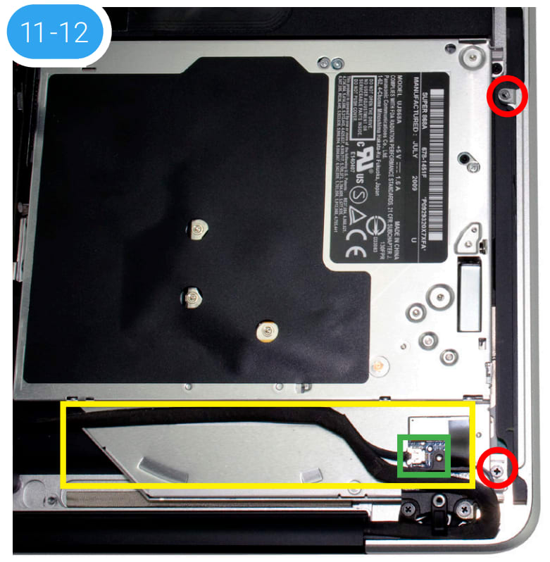
13. Once the cable and screws from the previous steps are removed, lift the optical drive along the top edge and gently pull it out of the optical bay.
Caution: take care to avoid snagging or pulling the cables that were disconnected in earlier steps. They can tear easily if they catch on the corners of the drive, as you lift it out of the chassis.
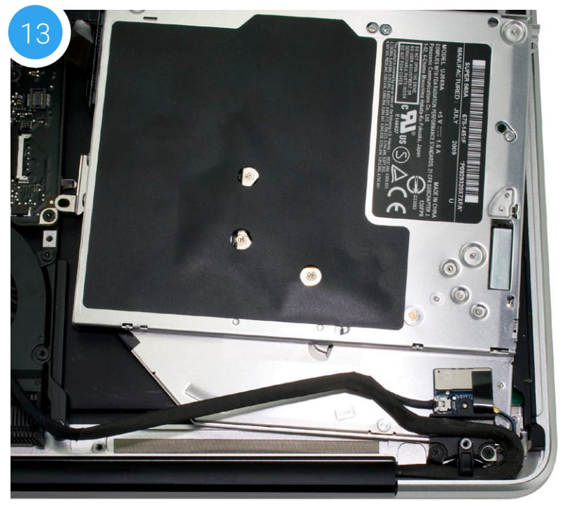
14. Place the optical drive and the assembled Data Doubler bracket in front of you, as shown below. Note: the cable and optical drive bracket from your laptop may look slightly different.
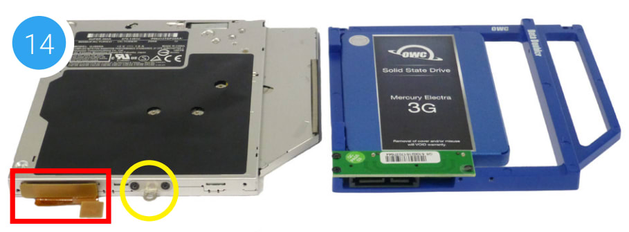
15. To transfer the optical drive cable (highlighted in red in Step 14) to the Data Doubler, first detach it from the drive by gently prying it loose with your fingernail or the nylon pry tool. Then gently pull the cable out of the SATA port. Caution: this cable is easily damaged.
16. Plug the cable into the Data Doubler’s green circuit board. The location of the installed cable is highlighted in red below.
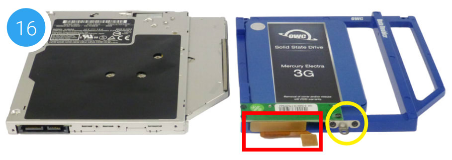
17. Remove the silver bracket that is attached to the back of the optical drive (highlighted in yellow in Step 16) by removing the two Phillips screws. Using the same two screws, affix the silver bracket to the OWC Data Doubler as shown in the photo from Step 16 (highlighted in yellow). Important: make sure the silver bracket is oriented the same way on the Data Doubler as it was on the optical drive.
18. Place the assembled Data Doubler into the optical bay, being careful not to damage any cables or connectors. Next, take two longer Phillips screws from the Kit and affix them in the same screw holes (highlighted in red) where you removed two shorter screws in Step 11.
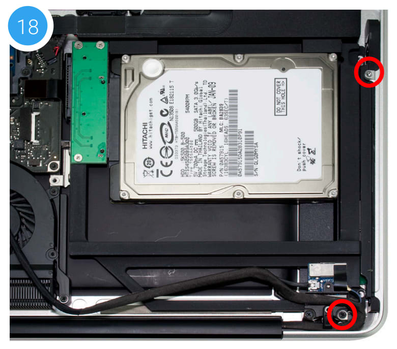
19. Re-align (and if applicable re-connect) the cable from Step 12. Next, affix the screw that was removed from the optical drive bracket in Step 9.
20. Carefully re-insert the cable you disconnected in Step 8, and reconnect the ribbon cable you disconnected in Step 10. If you disconnected your battery in Step 1, reconnect it now.
21. Replace the bottom cover that you removed earlier, snapping it back into place. Affix the 10 Phillips screws that were removed earlier. Make sure the three long screws are placed back in their original locations; check Step 2 if your laptop has a removable battery, or Step 4 if it does not.
The installation process is complete. Proceed to Section 3.1 Formatting for additional support information.
2.2.6 Mid-2010 15-inch MacBook Pro (6,2)
Important: Be sure that your laptop is fully shut down and disconnected from all cables, including the power cable.
1. Remove the 10 Phillips screws that hold the bottom cover to the chassis.
Note: the three right-most screws along the top edge (shown in yellow) are longer than the rest; install them in the same screw holes at the end of the process. The rest can be used interchangeably in the remaining screw holes.
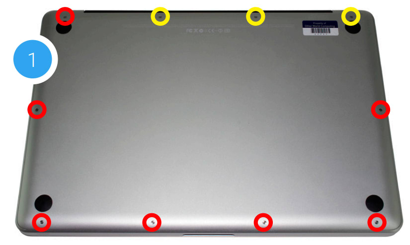
2. Once the screws are removed, place your fingers along the bottom cover near the black vent, then lift the cover. There are two snap clips attached to the cover that will release when you do this. Set the cover aside.
Recommended: before continuing, use a tri-lobe screwdriver (not included) to remove the three battery screws highlighted in red, then pull the battery tab so the battery stands up in the bay. Next use the nylon pry tool to gently push the connector towards the battery bay and out of its slot.
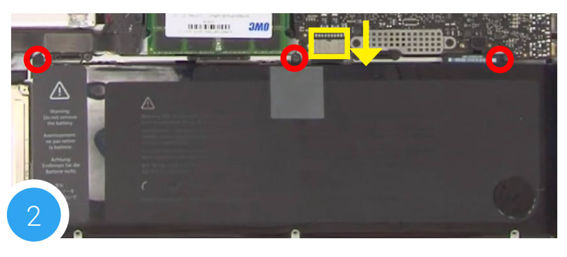
3. You should see the optical drive (indicated with arrow). This drive needs to be removed before you can install the OWC Data Doubler.
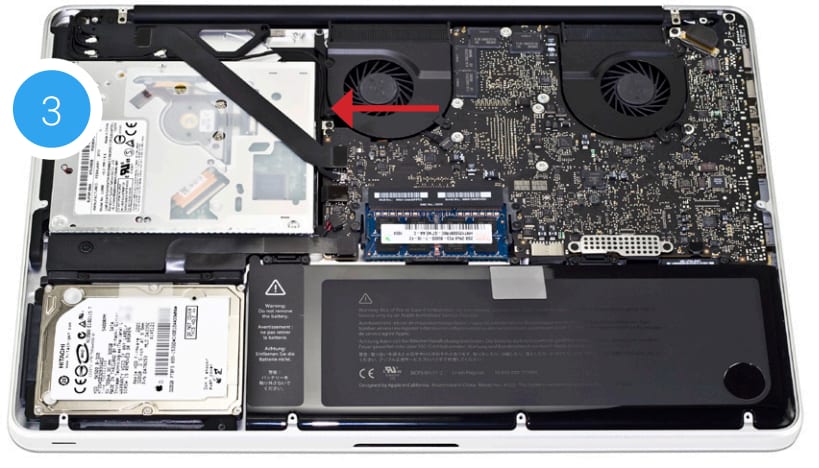
4. Rotate the laptop so the optical drive is oriented in the same manner as the drive shown.
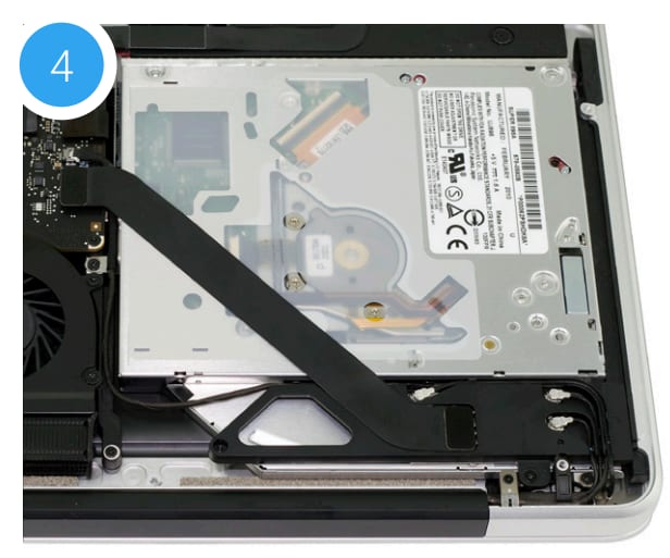
5. There are two ribbon cables along the left edge of the optical drive that are attached to the logic board, with a small silver cable located between them (highlighted in yellow). First, remove the small silver cable from the logic board by gently nudging the connector towards the optical drive.
Caution: this cable is easily damaged.
6. Just above and below the cable you disconnected in Step 5, are two ribbon cables attached to the logic board (highlighted in red). One connects to the optical drive, and one connects to the hard drive. Lift up gently on each cable using the included nylon pry tool, in order to disconnect the cables from the logic board. Caution: these cables are easily damaged.
7. Beneath the lower cable that is highlighted in red in Step 5, there is a silver bracket with a black Phillips screw affixed to it (highlighted in blue). Remove the screw and set it aside. It will be used during the reassembly process.
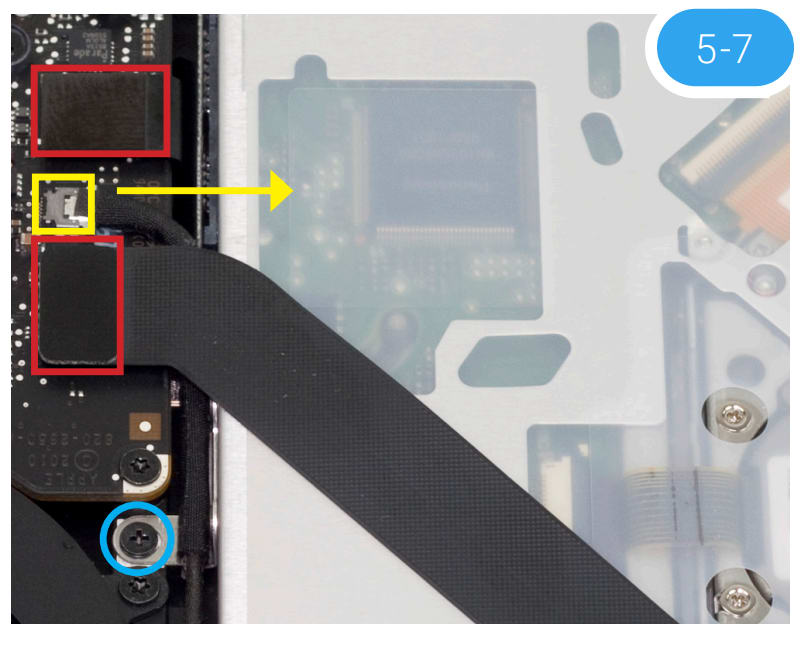
8. There is an Airport / Bluetooth bracket located below the optical drive. The bracket is connected to a black ribbon cable as well as three antennae (highlighted in yellow). Remove the two Phillips screws highlighted in red in order to detach the bracket, then carefully set it aside. You do not need to disconnect the cables. Note: the screw near the corner is longer than its counterpart; it needs to be affixed in the same location during reassembly
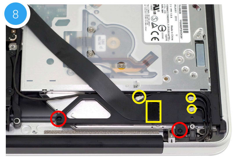
9. Remove the Phillips screw near the lower right corner of the optical drive. Note: You will not reuse this screw during reassembly; store it in a safe place in case you need it later.
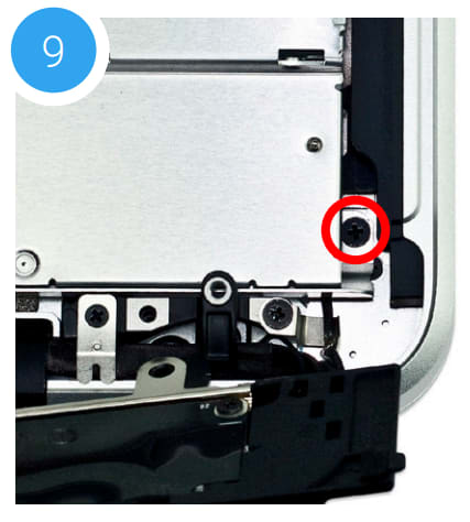
10. There is another small Phillips screw near the top of the optical drive (shown in red) that needs to be removed. Note: this screw will not be used during reassembly; store it in a safe place in case you need it later.
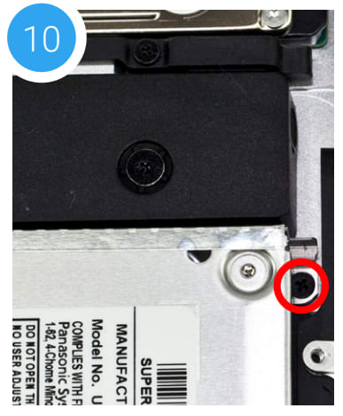
11. Lift the optical drive along the edge nearest the ribbon cables, then carefully remove it from the optical bay.
Caution: avoid snagging or pulling the cables that were disconnected in earlier steps. They can tear easily if they catch on the corners of the drive, as you lift it out of the chassis.
12. Place the optical drive you removed from your laptop and the hard drive that you already installed into the OWC Data Doubler bracket on the table in front of you, as shown.
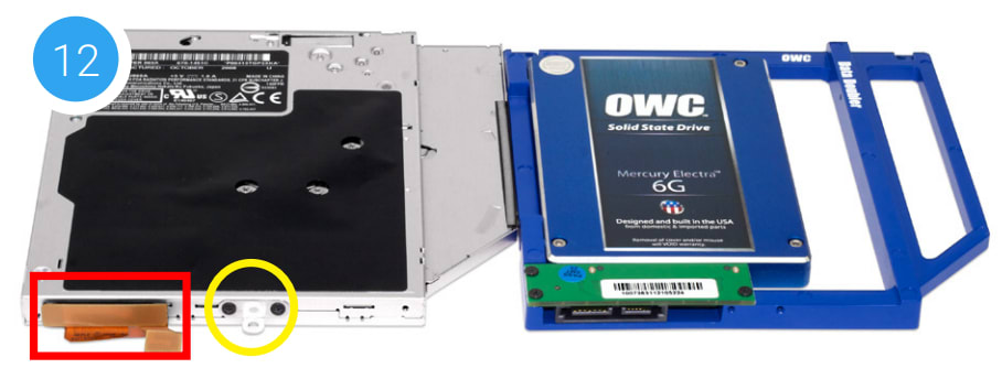
13. To transfer the optical drive cable (see area highlighted in red in Step 12) to the Data Doubler, first detach it from the drive by gently prying it loose with your fingernail or the nylon pry tool. Then gently pull the cable out of the SATA port. Caution: this cable is easily damaged.
14. Plug the cable into the Data Doubler’s green circuit board. The location of the installed cable is highlighted in red.
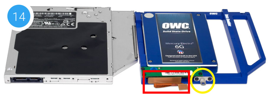
15. Remove the silver bracket that is attached to the back of the optical drive (highlighted in yellow in Step 12) by removing the two Phillips screws. Using the same two screws, affix the silver bracket to the OWC Data Doubler as shown in the photo from Step 14 (highlighted in yellow). Important: make sure the silver bracket is oriented the same way on the Data Doubler as it was on the optical drive.
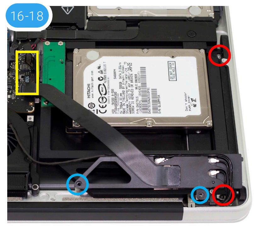
16. Carefully place the Data Doubler into the optical bay; Be careful not to damage any loose cables or connectors. Next, take two of the longer Phillips screws from the kit and affix them in the same locations (highlighted in red) where you removed the shorter screws in Steps 9 and 10.
17. Reseat the bracket and cable assembly you set aside in Step 8, then secure the screw you removed from the silver bracket in Step 7. Affix the two screws that were removed in Step 8 (highlighted in blue); the screw closer to the corner is longer and needs to be affixed in the same location. Make sure all the antenna connectors and the ribbon cable are still connected.
18. Reconnect the ribbon cables and the cable with the silver connector, that were disconnected in Steps 5 and 6 (area highlighted in yellow). If you disconnected your battery in Step 2, reconnect it now.
19. Carefully reseat the bottom cover, snapping it back into place. Affix the 10 Phillips screws that were removed earlier; make sure the three long screws are placed back in their original locations from Step 1.
The installation process is complete. Proceed to Section 3.1 Formatting for additional support information.
2.2.7 Early/Late 15-inch MacBook Pro (8,2) and Mid-2012 15-inch MacBook Pro (9,1)
Important: Be sure that your laptop is fully shut down and disconnected from all cables, including the power cable.
1. Remove the 10 Phillips screws that secure the bottom cover to the chassis.
Note: the three right-most screws along the top edge (shown in yellow) are longer than the rest; install them in the same screw holes at the end of the process. The rest can be used interchangeably in the remaining screw holes.
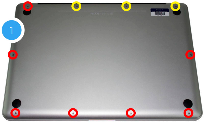
2. Once the screws are removed, place your fingers along the bottom cover near the black vent, then lift the bottom cover. There are two snap clips attached to the cover that will release when you do this. Set the cover aside.
3. You should see the optical drive (indicated by arrow). This drive needs to be removed before you can install the OWC Data Doubler. Recommended: before moving to the next step, use the nylon pry tool to gently lift the battery connector (highlighted in yellow) from the logic board.
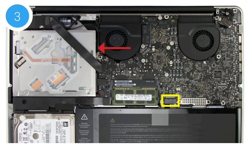
4. Rotate the laptop so the optical drive is oriented in the same manner as the drive shown.

5. There are two ribbon cables along the left edge of the optical drive that are attached to the logic board, with a small silver cable located beneath them (highlighted in yellow). First, remove the small silver cable from the logic board by gently nudging the connector in the direction shown.
Caution: this cable is easily damaged.
6. Lift up gently on each cable highlighted in red using the included nylon pry tool, in order to disconnect the cables from the logic board.
Caution: these cables are easily damaged.

7. Note that the cable that you disconnected in Step 5 is partly obscuring a silver bracket held in place by a black Phillips screw. Remove the screw and set it aside; you will need it during the reassembly process.
8. There is an Airport / Bluetooth bracket located below the optical drive. The bracket is connected to a black ribbon cable and four antenna connectors (highlighted in yellow). Remove the two Phillips screws highlighted in red to detach the bracket, then carefully set it aside. You do not need to disconnect the cables.
Note: the screw closer to the corner is longer; it needs to be affixed in the same location during reassembly.
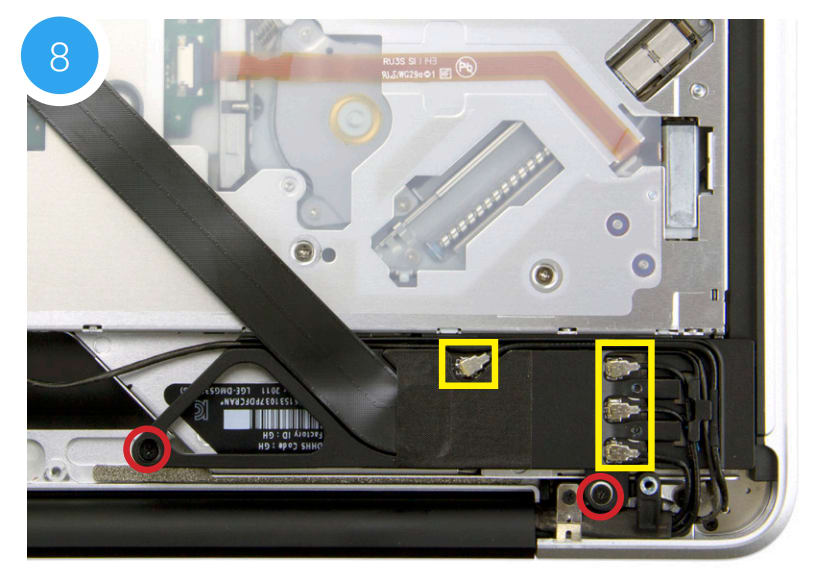
9. Remove the Phillips screw in the lower right of the optical drive. Note: You will not use this screw during reassembly; store it in a safe place in case you need it later.
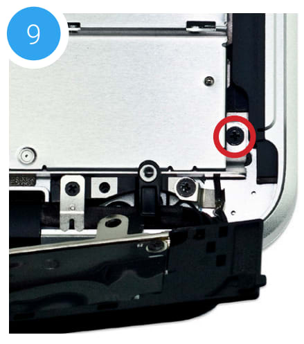
10. Near the top-right corner of the optical drive, there is another small Phillips screw that needs to be removed. Note: This screw will not be used during reassembly; store it in a safe place in case you need it later.
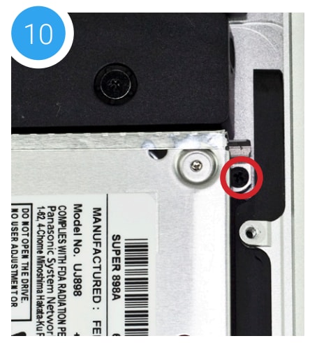
11. Gently lift the optical drive out of the optical bay, making sure not to damage any of the disconnected cables.
12. Place the optical drive you removed from your laptop and the hard drive that you already installed into the OWC Data Doubler bracket on the table in front of you, as shown below.
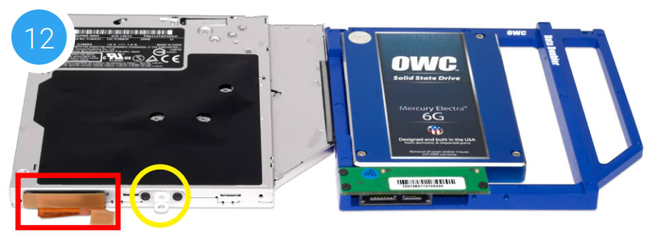
13. To transfer the optical drive cable (see area highlighted in red in Step 12) to the Data Doubler, first detach it from the drive by gently prying it loose with your fingernail or the nylon pry tool. Then gently pull the cable out of the SATA port. Caution: this cable is easily damaged.
14. Plug the cable into the Data Doubler’s green circuit board. The location of the installed cable is highlighted in red.
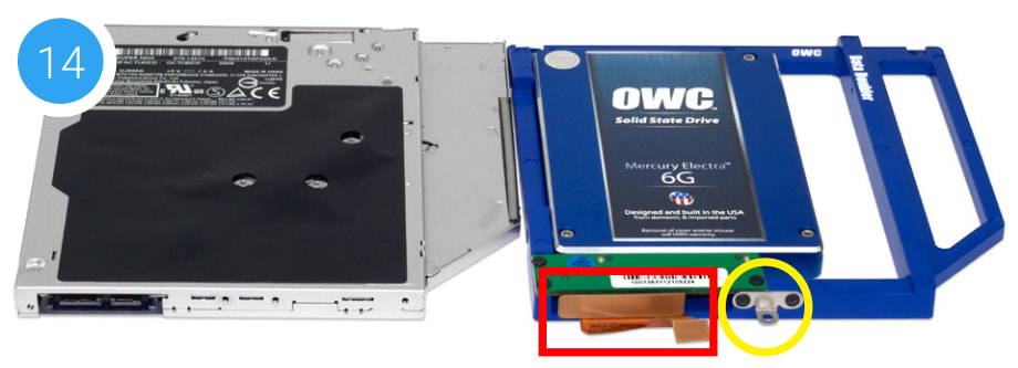
15. Remove the silver bracket that is attached to the back of the optical drive (highlighted in yellow in Step 12) by removing the two Phillips screws. Using the same two screws, affix the silver bracket to the OWC Data Doubler as shown in the photo from Step 14 (highlighted in yellow).
16. Carefully reseat the assembled Data Doubler into the optical bay, being careful not to damage any cables or connectors.
17. Take two longer Phillips screws from the kit and affix them in the same locations where the shorter screws were removed in Steps 8 and 9. Note: the location of the lower screw hole is obscured in this photo. Next, affix the screw that you removed from the silver bracket in Step 7.
18. Reseat the Airport / Bluetooth bracket and affix the screws that were removed in Step 7 (highlighted in green). Note: the longer screw should be affixed in the screw hole near the corner of the chassis. Make sure all the antenna connectors and the ribbon cable are still connected to the bracket.
19. Re-connect the ribbon cables and the cable with the silver connector, which you disconnected in Steps 5 and 6 (highlighted in yellow). If you disconnected your battery in Step 3, reconnect it now.
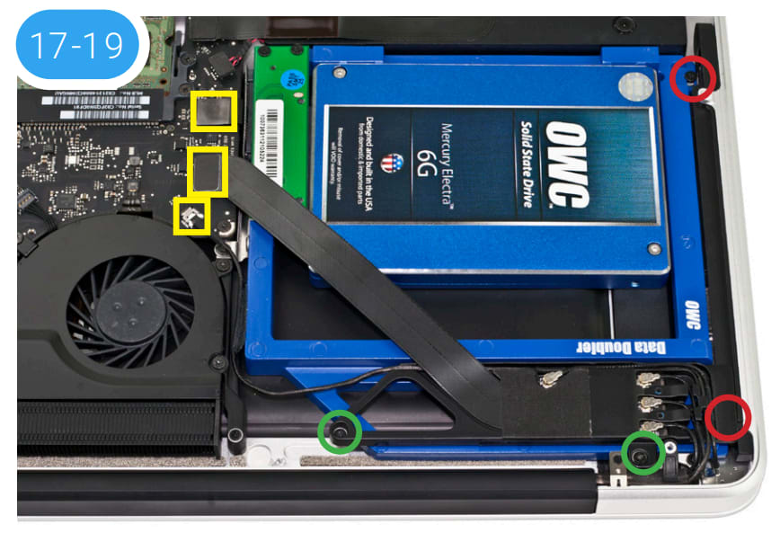
20. Carefully replace the bottom cover, snapping it back into place. Affix the 10 Phillips screws that were removed earlier. Make sure the three long screws are placed back in their original locations from Step 1.
The installation process is complete. Proceed to Section 3.1 Formatting for additional support information.
2.2.8 Early/Mid-2009 17-inch MacBook Pro (5,2)
Important: Be sure that your laptop is fully shut down and disconnected from all cables, including the power cable.
1. Remove the 10 Phillips screws that secure the bottom cover to the chassis.
Note: the three right-most screws along the top edge (shown in yellow) are longer than the rest; install them in the same screw holes at the end of the process. The rest can be used interchangeably in the remaining screw holes.
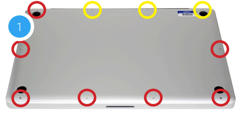
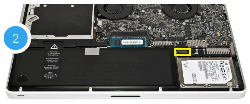
2. Place your fingers at the top of the chassis, near the black vent underneath the screen, then lift to release the bottom cover. There are two snap clips holding the cover in place; they will release when you lift the cover. The optical drive is noted by the red arrow and will need to be removed.
Recommended: before moving to the next step, gently pull on the plastic tab attached to the battery connector (highlighted in yellow) and dislodge it from the logic board.
3. Turn the laptop so that the optical drive is oriented as shown below. This matches the orientation used in later steps. There are two screws highlighted in red; remove the lower screw. Note: This screw will not be used during reassembly; store it in a safe place in case you need it later.
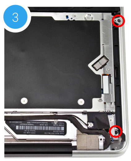
4. The second screw highlighted in Step 3 (top-right corner) is covering another screw that also needs to be removed. Use a Torx T8 driver to remove the top screw and the small bracket it holds in place. These screws will be used during the reassembly process.
5. Next, remove the screw that was hidden under the bracket (shown in red). Note: This screw will not be used during reassembly; store it in a safe place in case you need it later.
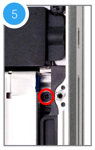
6. Near the corner of the optical drive, there is a black plastic bracket that screws into the side of the drive. You need to remove two Phillips screws that hold this bracket in place (shown in red) and set them aside. They will be used later in the reassembly process.
7. Once the bracket is disconnected, notice that the black cable bundle that runs along the body of the optical drive — it is attached via an adhesive. Gently lift and remove this cable bundle from the body of the optical drive.
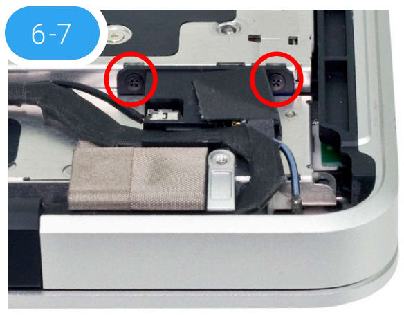
8. Near the left edge of the optical drive, there are two cables and a small plastic retainer that need to be disconnected from the logic board before you can proceed. First, use a corner of the included nylon pry tool to gently dislodge the small plastic retainer. Highlighted in red, the intact retainer is partly obscured in this photo.
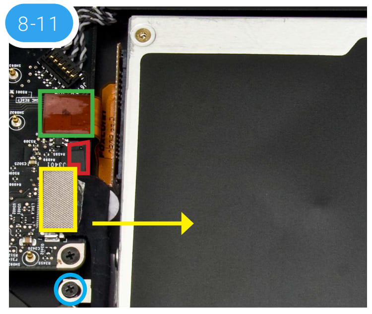
9. Next, remove the black cable with the silver connector (highlighted in yellow) by gently pushing the connector in the direction shown above, until it disconnects from the logic board.
10. In many cases, the black cable will obscure a small black Phillips screw (highlighted in blue). This screw is connected to a metal bracket that helps to hold the optical drive in place. Remove the screw and set it aside; it will be used during reassembly.
11. Just above the spot where the silver connector was attached to the logic board in Step 9, there is an orange ribbon cable (highlighted in green). Note: this cable may be black in some cases. The cable connects the optical drive to the logic board. Use the nylon pry tool to gently lift the ribbon cable’s connector off the logic board. Caution: this cable is easily damaged.
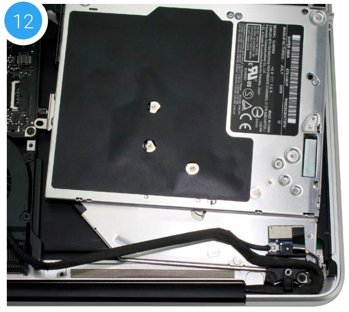
12. Once the cables, retainer, and screw have been removed, hold the optical drive along the edge nearest the cable connectors, then gently lift the drive out of the optical bay.
Caution: take care to avoid snagging or pulling the cables that were disconnected in earlier steps. They can tear easily if they catch on the corners of the drive as you lift it out of the chassis.
Note: the appearance of your drive and optical bay may vary slightly
13. Place the optical drive and the assembled Data Doubler bracket in front of you. Note: the cable and optical drive bracket from your laptop may look slightly different.
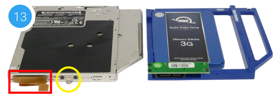
14. To transfer the optical drive cable (highlighted in red in Step 13) to the Data Doubler, first detach it from the drive by gently prying it loose with your fingernail or the nylon pry tool. Then gently pull the cable out of the SATA port. Caution: this cable is easily damaged.
15. Plug the cable into the Data Doubler’s green circuit board. The location of the installed cable is highlighted in red.

16. Remove the silver bracket that is attached to the back of the optical drive (highlighted in yellow in Step 13) by removing the two Phillips screws. Using the same two screws, affix the silver bracket to the OWC Data Doubler as shown in the photo from Step 15 (highlighted in yellow). Important: make sure the silver bracket is oriented the same way on the Data Doubler as it was on the optical drive.
17. Place the assembled Data Doubler into the optical bay. Be careful not to damage any loose cables or connectors. Next, take one of the longer screws from the kit and replace the screw that was removed in Step 5 (shown in red).
18. Use another of the longer screws to replace the screw that was removed in Step 3. Then, reattach the bracket from Step 4 with the original screw that came with the laptop (shown in blue).
19. Affix the screw removed in Step 10 to the optical drive bracket (shown in yellow).
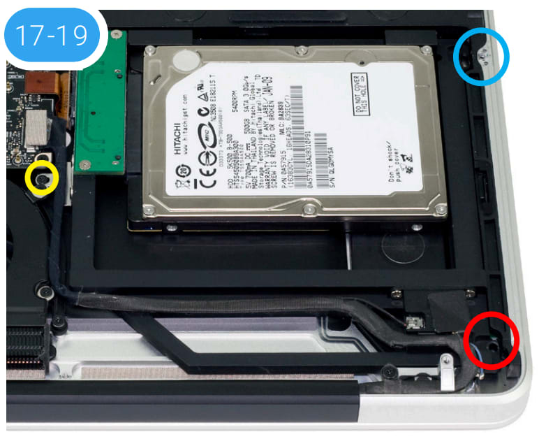
20. Carefully reconnect the cable that was disconnected in Step 9, then reconnect the ribbon cable that was disconnected in Step 11. Next, attach the retainer that was dislodged in Step 8. If you disconnected your battery in Step 2, reconnect it now.
21. Carefully replace the bottom cover, snapping it back into place. Affix the 10 Phillips screws that were removed earlier; make sure the three long screws are placed back in their original locations from Step 1.
The installation process is complete. Proceed to Section 3.1 for additional support information.
2.2.9 Mid-2010 17-inch MacBook Pro (6,1) and 2011 17-inch MacBook Pro (8,3)
Important: Be sure that your laptop is fully shut down and disconnected from all cables, including the power cable.
1. Remove the 10 Phillips screws that secure the bottom cover to the chassis. Note: This section will show the MacBook Pro 6,1 installation process.
Note: the three right-most screws along the top edge (shown in yellow) are longer than the rest; install them in the same screw holes at the end of the process. The rest can be used interchangeably in the remaining screw holes.
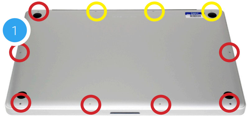
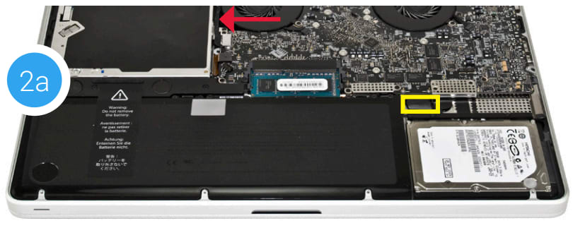
2. Place your fingers along the bottom cover, near the black vent underneath the screen, then lift to release the bottom cover. There are two snap clips holding the cover in place; they will release when you lift the cover. Set the cover aside. The optical drive is indicated below by the white arrow; it needs to be removed. Recommended: before moving to the next step, gently pull the plastic tab attached to the battery connector (shown in yellow) and dislodge it from the logic board.
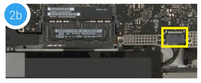
Note: If you are using a MacBook Pro 8,3 your battery connector will look like the one highlighted below in yellow (photo 2b). Use the nylon pry tool to carefully lift the connector off the logic board before proceeding.
3. Using the nylon pry tool, disconnect the cable with the silver connector (shown in yellow) from the logic board by gently applying pressure in the direction shown below. Note: this cable obscures a screw that will be removed in an upcoming step. Caution: this cable is easily damaged.
4. Just above the silver connector that was disconnected in Step 3, there is a black ribbon cable connector (shown in red). Use the nylon pry tool to disconnect it from the logic board by applying gentle upward pressure.
5. Use the nylon pry tool to gently lift the orange ribbon cable (highlighted in blue) from the logic board. Caution: this cable is easily damaged.
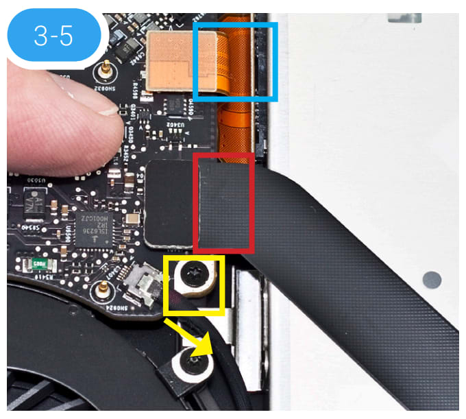
6. Set aside the black cable that you disconnected in Step 3. Note the metal bracket that is attached to the optical drive, helping to secure it in place. Remove the black Phillips screw (shown in red) that holds this bracket in place. This screw will be used during the reassembly process.
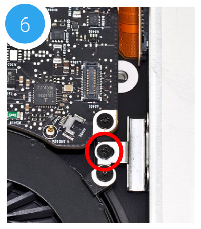
7. At the rear of the optical drive there is an Airport / Bluetooth bracket that has a flexible ribbon cable and three antenna connectors. Remove the two Phillips screws that are circled in red below. Note: the screw closer to the corner of the chassis is longer; it needs to be affixed in the same location during reassembly.
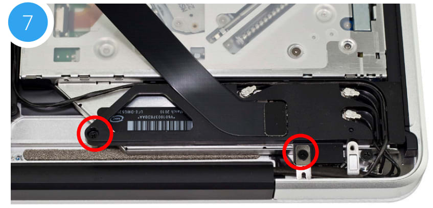
8. Gently lift the Airport / Bluetooth bracket up and away from the corner of the chassis; this will expose a Phillips screw that secures the optical drive to the chassis. You do not need to disconnect any of the cables. If one comes loose carefully reattach it now or during reassembly.
9. Once the bracket has been set aside, remove the black Phillips screw highlighted below in red. Note: This screw will not be reused during reassembly; put it in a safe place in case you need it later.
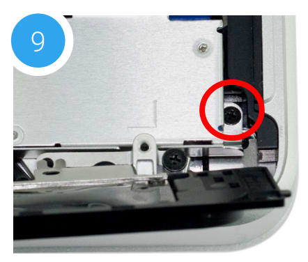
10. At the top right of the optical drive, there is another small Phillips screw that needs to be removed. Note: This screw will not be reused during reassembly; put it in a safe place in case you need it later.
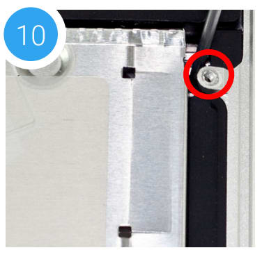
11. Lift up the edge of the optical drive nearest the ribbon cables and gently remove it from the optical bay. Be careful not to damage any of the cables or connectors.
12. Place the optical drive and the assembled Data Doubler bracket in front of you, as shown. Note: the cable and optical drive bracket from your laptop may look slightly different.
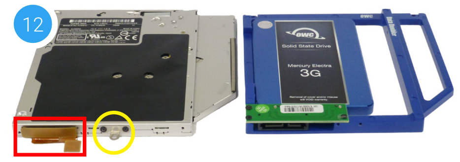
13. To transfer the optical drive cable (see area highlighted in red in Step 12) to the Data Doubler, first detach it from the drive by gently prying it loose with your fingernail or the nylon pry tool. Then gently pull the cable out of the SATA port. Caution: this cable is easily damaged.
14. Plug the cable into the Data Doubler’s green circuit board. The location of the installed cable is highlighted in red.
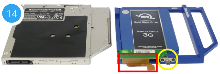
15. Remove the silver bracket that is attached to the back of the optical drive (highlighted in yellow in Step 12) by removing the two Phillips screws. Using the same two screws, affix the silver bracket to the OWC Data Doubler as shown in the photo from Step 14 (highlighted in yellow). Important: make sure the silver bracket is oriented the same way on the Data Doubler as it was on the optical drive.
16. Carefully place the assembled Data Doubler into the optical bay. Be careful not to damage the cables or connectors. Next, take two of the longer screws from the kit and affix them in the same screw holes where shorter screws were removed in Steps 9 and 10 (locations shown in red).
Note: this image shows an earlier Data Doubler that uses black aluminum.
17. Reseat and affix the Airport / Bluetooth bracket that was removed in Steps 7 and 8. The screw locations are highlighted in blue; make sure the longer screw is affixed to the location nearer the corner of the chassis.
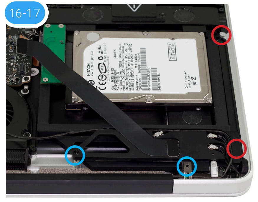
18. Affix the screw that was removed from the aluminum bracket in Step 6.
19. Reconnect the cables that were disconnected in Steps 3, 4, and 5. If you disconnected the battery in Step 2, reconnect it now.
20. Carefully replace the bottom, snapping it back into place. Affix the 10 Phillips screws that were removed earlier; make sure the three long screws are placed back in their original locations from Step 1.
The installation process is complete. Proceed to Section 3.1 for additional support information.
Support Resources
3.1 Formatting Tips
For tips on formatting your newly installed drive, please visit: www.owcdigital.com/format
3.2 Troubleshooting
For cases where the battery was removed during installation, you will need to reset the date and time on your Mac before using it. Choose System Preferences > Date & Time, make the desired settings, then restart.
If you're having trouble installing the Data Doubler, re-examine each step. The most common cause of installation-related issues can be traced to a missing step or screw.
Some users have reported that the ribbon cable connecting the optical drive is difficult to remove, or that it is wedged beneath the edge of the logic board. A business card, cut in half lengthwise is a perfect fit to slide between the logic board and the cable. Lift the ribbon cable from the logic board using your fingernail or a nylon pry tool and gently lift the cable to allow the business card to slide down between the logic board and cable. If you are still having trouble, see 24/7 Support Chat.
Changes
The material in this document is for information purposes only and subject to change without notice. While reasonable efforts have been made in the preparation of this document to assure its accuracy, OWC, its parent, partners, affiliates, officers, employees, and agents assume no liability resulting from errors or omissions in this document, or from the use of the information contained herein. OWC reserves the right to make changes or revisions in the product design or the product manual without reservation and without obligation to notify any person of such revisions and changes.
FCC Statement
Warning! Modifications not authorized by the manufacturer may void the user’s authority to operate this device. Note: This equipment has been tested and found to comply with the limits for a Class A digital device, pursuant to Part 15 of the FCC Rules. These limits are designed to provide reasonable protection against harmful interference when the equipment is operated in a commercial environment. This equipment generates, uses, and can radiate radio frequency energy and, if not installed and used in accordance with the instruction manual, may cause harmful interference with radio communications. Operation of this equipment in a residential area is likely to cause harmful interference, in which chassis the user will be required to correct the interference at his own expense.
Note: This equipment has been tested and found to comply with the limits for a Class B digital device, pursuant to Part 15 of the FCC Rules. These limits are designed to provide reasonable protection against harmful interference in a residential installation. This equipment generates, uses and can radiate radio frequency energy and, if not installed and used in accordance with the instructions, may cause harmful interference to radio communications. However, there is no guarantee that interference will not occur in a particular installation. If this equipment does cause harmful interference with radio or television reception, which can be determined by turning the equipment off and on, the user is encouraged to try to correct the interference by one or more of the following measures:
- Reorient or relocate the receiving antenna.
- Increase the separation between the equipment and receiver.
- Connect the equipment to an outlet on a circuit different from that to which the receiver is connected.
Health And Safety Precautions
- Use proper anti-static precautions while performing the installation of your hard drives into this drive enclosure. Failure to do so can cause damage to your drive mechanisms and/or the hard drive enclosure.
- Read this user guide carefully and follow the correct procedures when setting up the device.
- Do not attempt to disassemble or modify the device. To avoid any risk of electrical shock, fire, short circuiting or dangerous emissions, never insert any metallic object into the device. If it appears to be malfunctioning, contact technical support.
- Never expose your device to rain, or use it near water or in damp or wet conditions. Never place objects containing liquids on the drive, as they may spill into its openings. Doing so increases the risk of electrical shock, short-circuiting, fire or personal injury.
General Use Precautions
- To avoid damage, do not expose the device to temperatures outside the range of 5° C to 40° C (41° F to 104° F).
- Do not place heavy objects on top of the device.
- Protect your device from excessive exposure to dust during use or storage. Dust can build up inside the device, increasing the risk of damage or malfunction.
- For up-to-date product and warranty information, please visit the product web page.
Copyrights and Trademarks
No part of this publication may be reproduced, stored in a retrieval system, or transmitted in any form or by any means, electronic, mechanical, photocopying, recording or otherwise, without the prior written consent of OWC.
© 2020 Other World Computing, Inc. All rights reserved. OWC and Data Doubler are a trademarks of New Concepts Development Corporation, registered in the U.S. Patent and Trademark Office and/or in Canada. The OWC logo is a trademark of New Concepts Development Corporation. Apple, Mac, MacBook, MacBook Pro, and OS X are trademarks of Apple Inc., registered in the United States and other countries. Other marks may be the trademark or registered trademark property of their owners.
Free Support Chat
Our free award-winning support team is ready to answer all of your questions. Technical support is available Monday - Friday: 9AM - 6PM. Customer Support & Sales is available Monday - Friday: 8AM - 8PM. Support is unavailable on U.S. Federal holidays. Talk to a human today.


 1-800-275-4576