MAXPower eSATA 6G-4e PCIe 2.0 Controller Card
User Guide

Introduction
1.1 About This Manual
The images and descriptions may vary slightly between this manual and the unit shipped. Functions and features may change depending on the firmware or driver version. Please visit the product web page for the most recent product specifications.
1.2 Package Contents
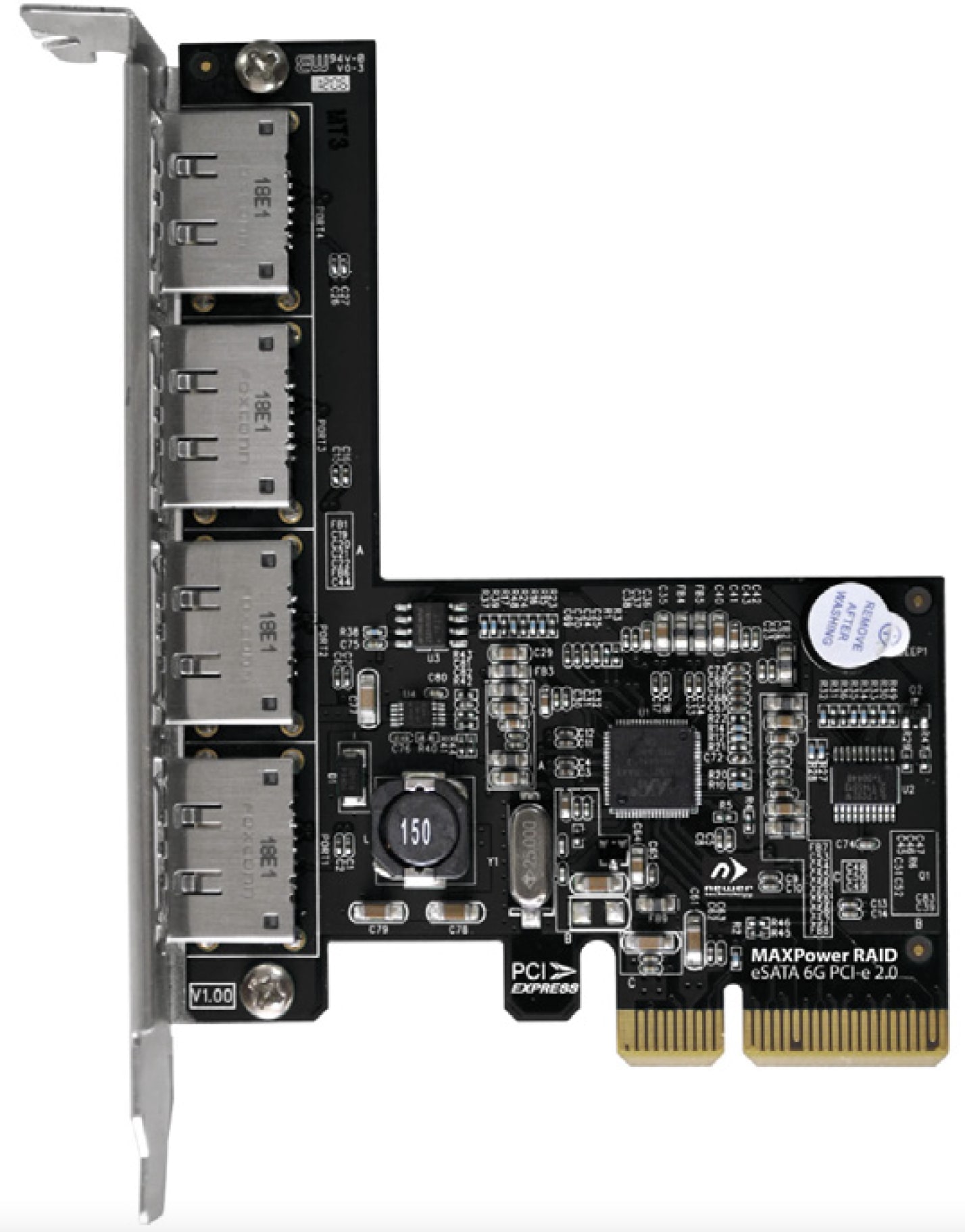
- 1 MAXPower eSATA 6G-4e PCIe 2.0 Controller Card
Not Pictured: Quick-Start insert providing links to the latest drivers and information.
1.3 System Requirements
Apple Mac
- Hardware: Intel-based Mac with a PCIe 2.0 or 1.0 slot, or a Thunderbolt PCIe expansion chassis
- OS: Driver requires OS X 10.6.8-10.11.5 or macOS 10.12-10.13
- Web Browser: Firefox or Chrome recommended
PC
- Hardware: PC with an 8x PCIe 2.0 or 1.0 slot, or a Thunderbolt PCIe expansion chassis
- OS: Driver requires Windows® Vista or later
Web Browser: Firefox or Chrome recommended
Device Setup
2.1 Raid Modes
RAID stands for Redundant Array of Independent Disks. It is a logical grouping of two or more identical drives, configured to achieve a single logical volume that can be larger, faster, and which provides more data redundancy than the individual volumes used to create it. Your MAXPower eSATA 6G-4e RAID Controller Card supports the following RAID modes:
JBOD (Independent and SPAN Modes) - when set to Independent Mode, the full capacity of each disk is available for individual use. This mode is appropriate when maximum flexibility is required, typically each disk is used for a different purpose. Independent Mode provides no significant speed gains or data protection. When set to SPAN Mode, the capacity of each disk is combined into a single volume. Similar to Independent Mode, SPAN provides no significant speed gains or data protection.
RAID 0 “Stripe” - appropriate for workflows that require high volume storage at maximum speed. The capacity of two or more identical disks are combined into a single logical volume. Data is written to and/or read from multiple disks simultaneously. RAID 0 provides no data protection. If one drive fails, all data is lost! Be sure all important data stored on a RAID 0 is backed up elsewhere.
RAID 1 “Mirror” - appropriate for workflows that require a high degree of data redundancy but which do not require high speed data transfers. The capacity of two or more identical disks are combined into a single logical volume. One drive can fail and all data will still be accessible. The capacity available is equal to the size of a single disk in the array.
RAID 5 “Stripe + Protection” - this mode provides a balance of speed optimizations, increased capacity, and data protection. Data is striped like in a RAID 0, so significant speed gains are seen. However, RAID 5 also Utilizes mathematical parity to achieve data protection in way that is more space-efficient than RAID 1. One drive can fail and all data will still be accessible, and the array can be rebuilt.
RAID 10 / RAID 50 “Mirrored Stripe” - this setup takes two identical RAID 1 arrays or RAID 5 arrays and “stripes” them to improve data transfer speeds. 1-2 drives can fail and be replaced, depending on which mode you’re using and which drive(s) failed.
2.2 Hardware Installation
Attention: Observe Precautions For Handling Electrostatic Sensitive Devices
Before Installing the MAXPower eSATA 6G-4e card, make sure computer is turned off and unplugged from its power source. Take appropriate electrostatic discharge precautions, as your computer is a static-sensitive device. It is susceptible to invisible damage if not protected during installation
We recommend proper grounding by using a grounding strap. Make sure to work in a clean and static-free area, and avoid wearing clothing that retains static charges.
- STEP 1 Open the computer or PCIe chassis and locate an unused PCIe 2.0 or 1.0 slot.
- STEP 2 Remove the PCIe slot cover.
- STEP 3 Carefully align the MAXPower card with the PCIe slot and press down gently.
- STEP 4 After installing the MAXPower card, close the computer or chassis. Then restart your computer.
- STEP 5 Once the operating system has loaded, download and install the latest driver and software, as described in Section 2.3 (below).
2.3 Software Installation
Follow the steps below to install the required drivers and RAID Management software for your MAXPower mini-SAS cards.
2.3.1 OS X – Driver And Raid Management Software Installation
- Download the latest installer file from www.newertech.com/support#data Look for the “DMG” file link shown with the MAXPower eSATA 6G-4e card.
- Double-click the .dmg file to mount the disk image that contains the OS X driver and RAID Management application.
- Next, double-click on the installer package labeled “MAXPower_RAID_eSATA_6G_PCIe_2_0_Controller.pkg”.
- Follow the on-screen steps to complete the installation process. After the install has completed you will be prompted to restart the computer – this is required.
2.3.2 Windows Vista Or Later - Driver Installation
- Download the latest installer file from www.newertech.com/support#data Look for the “ZIP” file link shown with the MAXPower eSATA 6G-4e card. Unzip the file.
- Click on the Windows Start menu then right click on Computer and select Properties.
- From the System Screen, click the Device Manager link on the left side of the window. Within the Device Manager window, under Other Devices, the MAXPower RAID Card will appear with a warning symbol.
- Right click on the MAXPower RAID Card icon and select Update Driver Software... .
- Next, click on Browse my computer for driver software.
- Navigate to and open the unzipped folder named MaxPower_RAID_4eSATA_Win.
- Make sure the Include Sub-folders option is checked, then click Next.
- When asked “Would you like to install this driver software,” click Install.
- Once the installation is complete, click the option to restart your computer – this is required.
2.3.3 Windows Vista Or Later - Raid Management Software Installation
- From the unzipped folder noted in step 6 above, browse to the sub-folder called RAID Management application.
- Run the Setup file.
- Once the setup is complete restart the computer.
2.4 RAID Management Software
After installing your RAID hardware and installing the appropriate drivers and software, you can use the Newer RAID Management application to create RAID arrays and JBOD configurations, and to monitor the health and performance of your physical disks. The components of the Newer RAID Management application are described throughout this section.
Note: RAID Management can be accessed from most modern web browsers but Chrome or Firefox are recommended.
For Windows operating systems, type the following address into the URL bar:
http://localhost:7402/
For OS X, use this address:
http://localhost:8402/
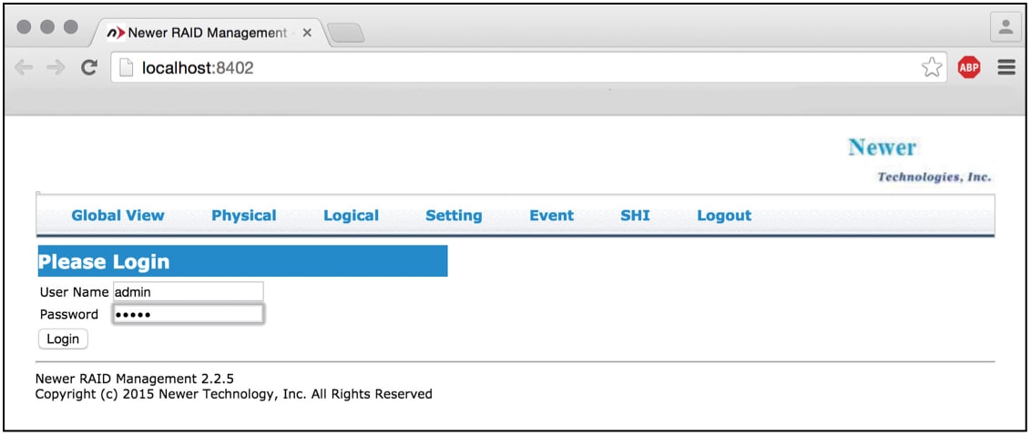
When prompted for a user name and password, enter the names shown below. Note: the password can be changed at any time using the Change Password option in the Setting panel.
User Name: admin
Password: admin
2.4.1 Global Information
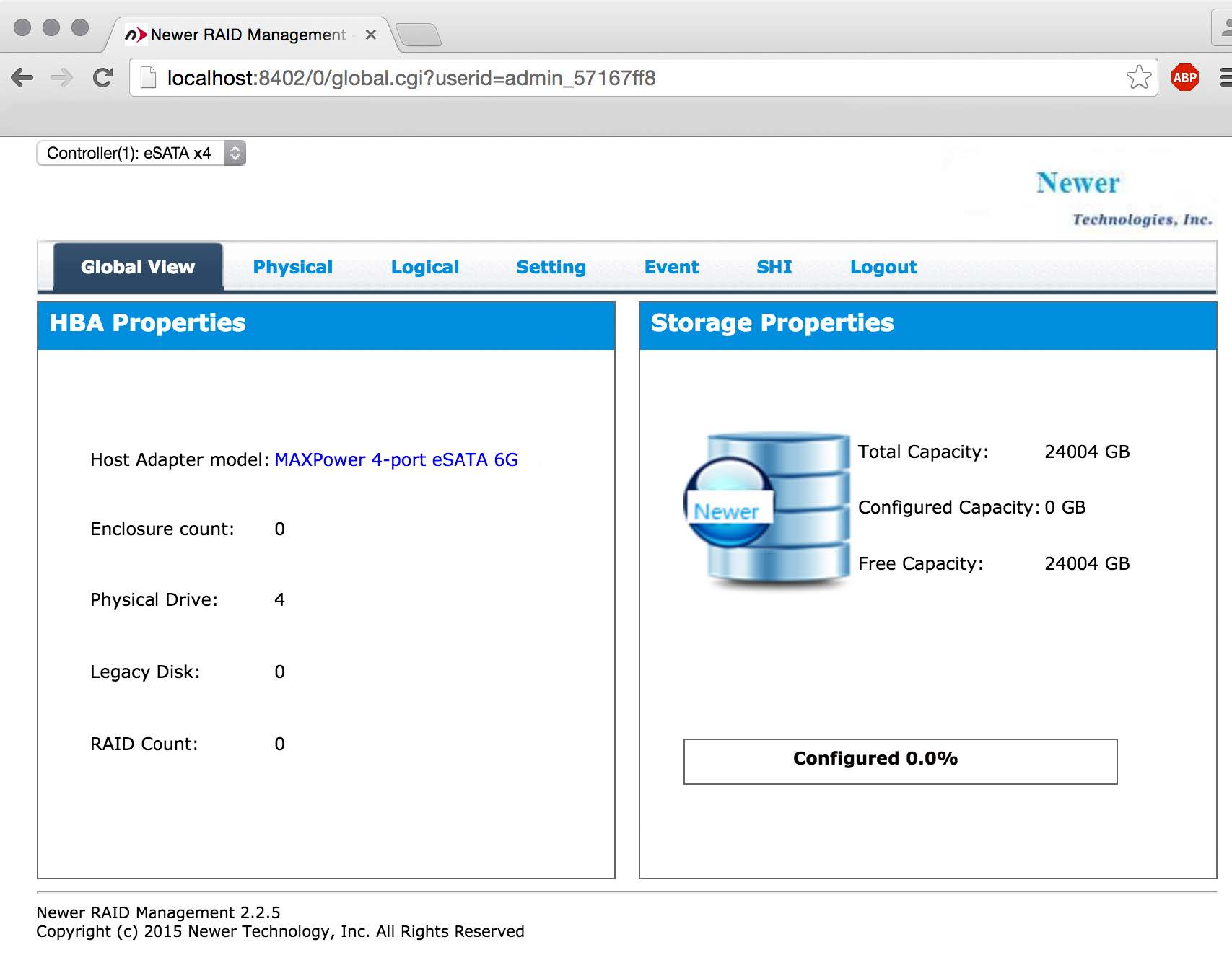
The following information is available from the Global view, which is the default screen for Newer RAID Management. This view is for informational purposes only. It is not used to configure or monitor the available disks.
HBA Properties
- Host Adapter Model – the type of RAID controller card detected.
- Enclosure Count – the total number of drive enclosures connected to your MAXPower controller card.
- Physical Drive – the total number of physical drives detected by the controller card.
- Legacy Disk – the total number of physical drives previously formatted by another utility.
- RAID Count – the total number of logical arrays detected.
STORAGE Properties
- Total Capacity – the total capacity of all detected SSDs and HDDs that are detected.
- Logical Capacity – the total capacity of all logical drives and arrays that are available.
- Free Capacity – the total remaining capacity that is available for inclusion in a JBOD or additional RAID arrays.
2.4.2 Physical Disk Properties
Information and options relating to your MAXPower RAID controller card and the connected drives are available from this panel.
Controller
Clicking the Controller link in the sidebar will provide basic information about the model of the controller card, its firmware version, as well as the PCIe bus where it is located and other details.
Devices
Clicking the Devices sidebar link provides a detailed list of all physical disks currently detected by the controller card and RAID Management. Using the screenshot below as an example, there are four 6TB disks detected.

If you click one of the device links displayed under Physical Devices Information, more detail is provided about that specific disk. For this example, the link for Device_1_5 was clicked. See below for more information about what each option does.

A. Click the Unplug link to power off the device, should you need to remove it from the enclosure.
B. Read Ahead is a feature available in many disks to improve read performance. The default setting is Enabled.
C. Write Cache is a feature available in many disks to improve write performance. The default setting is Enabled.
D. NCQ (Native Command Queuing) is a feature available in many disks to improve order of operations performance. The default setting is Enabled.
E. Click the “ON” link next to Identify LED, to temporarily activate the LED on the enclosure which represents the selected disk.
2.4.3 Logical Disk Operations
Use this panel to create, delete, rebuild, or modify logical arrays (or independent volumes). The default view is shown below.
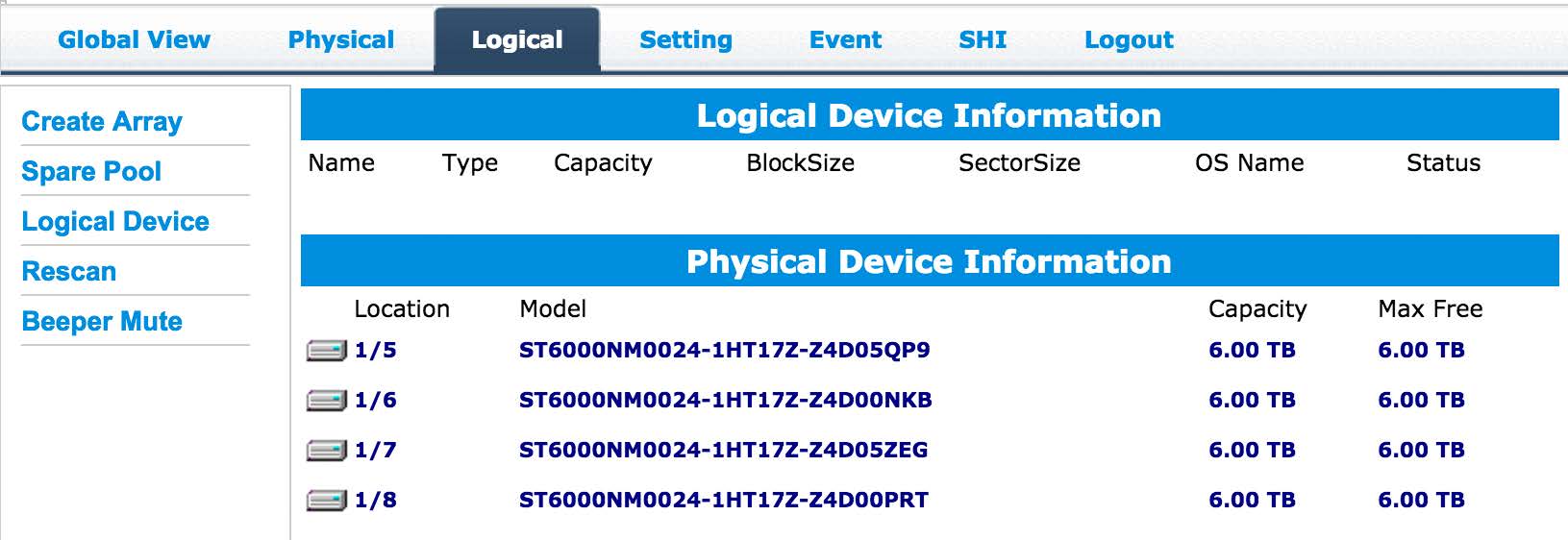
Create Array
Click the Create Array link in the sidebar when you need to build an array from two or more available disks. IMPORTANT: it is strongly recommended that you back up any important data from the available disks before you begin this process.
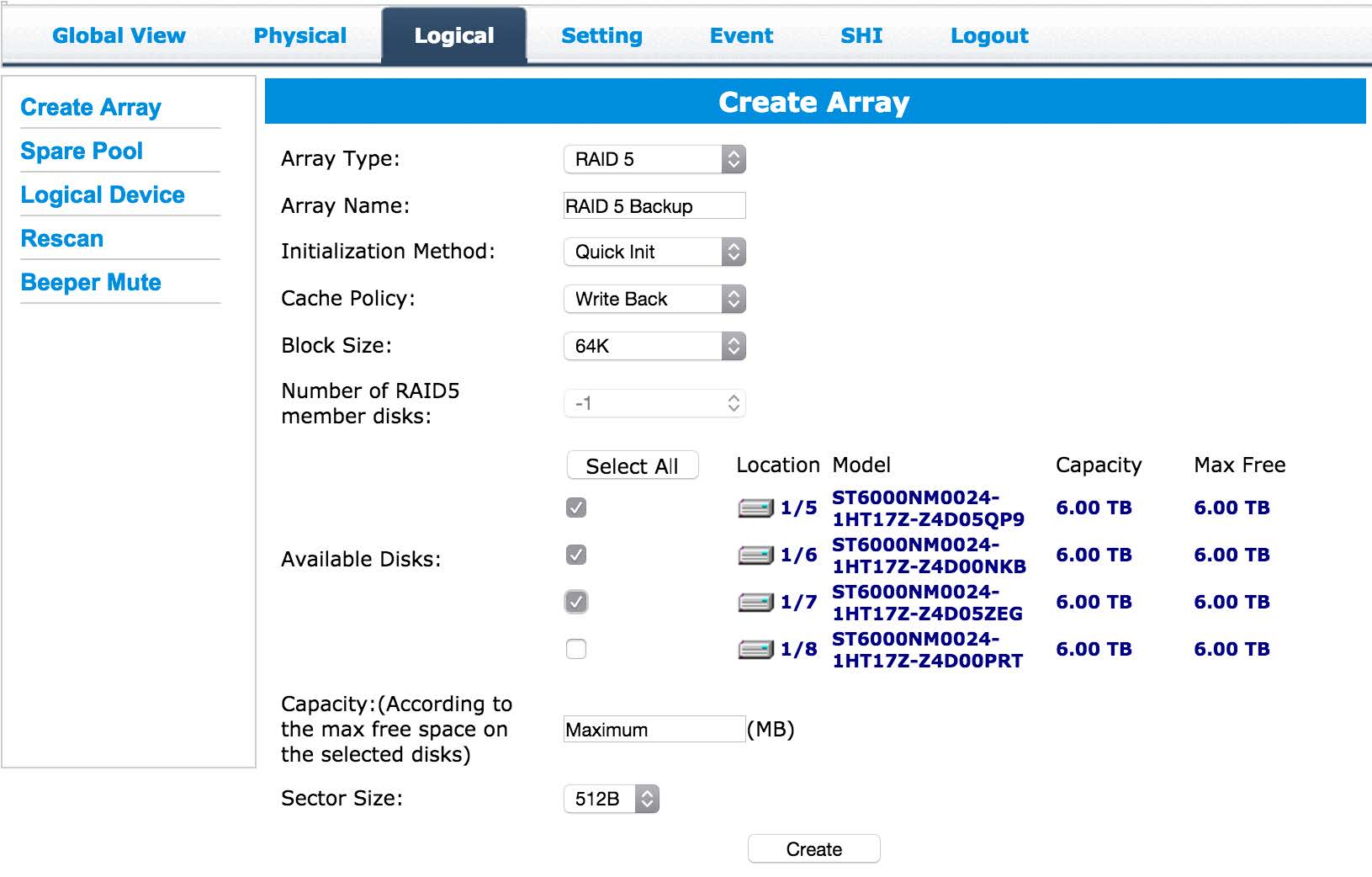
Array Type – the options are JBOD and RAID 0, 1, 5, 1/0 (also called RAID 10), and 5/0 (also called RAID 50). See Section 2.1 for more information about each RAID type. NOTE: the RAID mode you choose will determine which settings are available.
Array Name – use this text field to name the new array.
Initialization Method – by default this option is set to Keep Old Data. This method works around existing data on the available disks and does not perform any initialization of the array. For this reason we do not recommend the Keep Old Data option, if it can be avoided.
Instead, make sure your data is backed up elsewhere, then choose the Foreground method for initialization. This will delete all content, making the full capacity of each disk available to the array and avoiding potential performance or legacy data loss issues. This is this fastest option for initializing the disks but they will not be available for use during the process.
If necessary you can also use the Background method, which will produce the same result as Foreground, however it is a slower process due to the fact that you can access the array before the full initialization is complete.
Cache Policy – this setting determines how data is written to the array. The Write Back option provides greater performance but a lower degree of data integrity. Data can be lost during power failures, kernel panics or other unusual conditions. The Write Through option provides additional data integrity during these same unusual conditions by writing data directly to disk.
Block Size – determines the size of the data blocks on the array. The default of 64K works well for most general computing purposes. For high resolution video workflows you may want to set this to a higher value, while database work may benefit from lower values.
Once you’ve applied your settings and within a few seconds of clicking the Create button on the Create Array screen, you should see a new logical volume appear as well as an initialization screen from the operating system’s default disk formatting utility. To format the array you can follow the screen prompts from your OS utility and format the new logical volume.
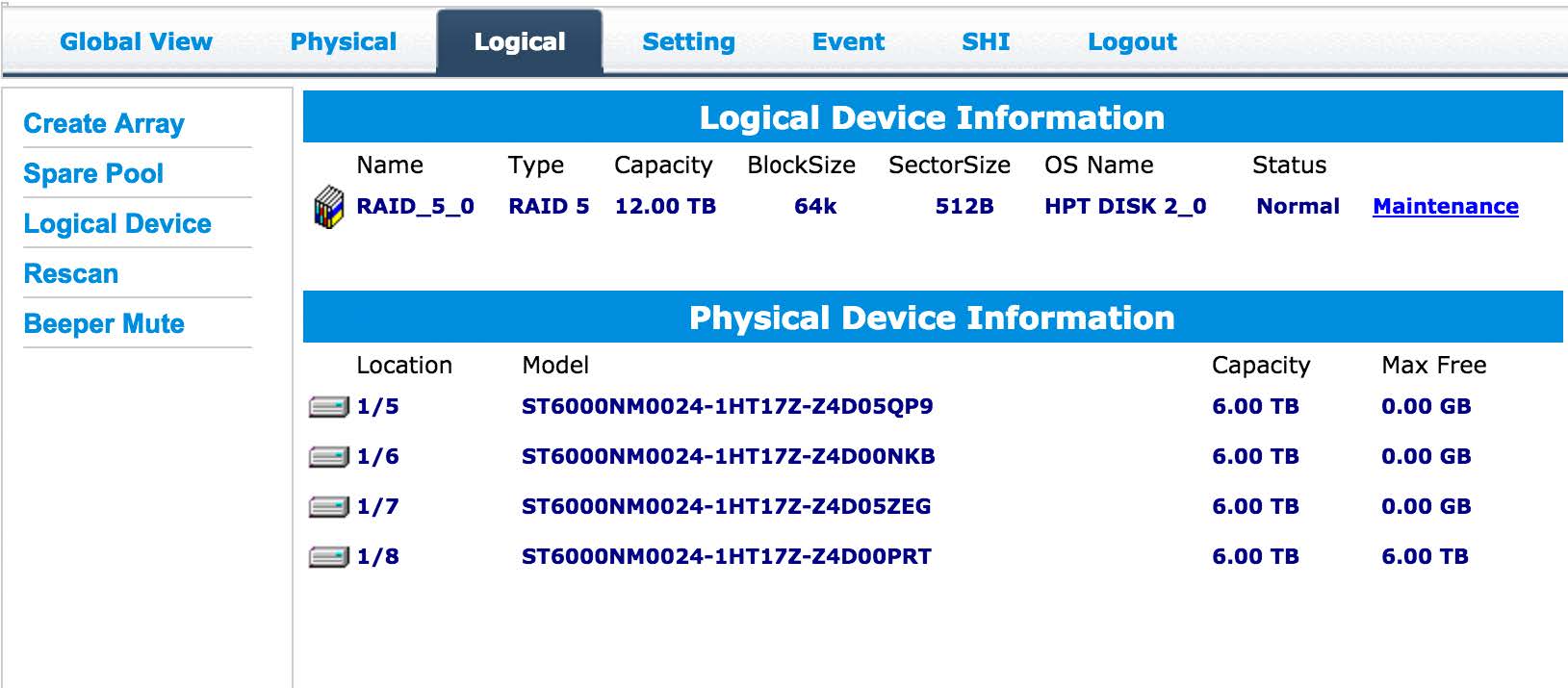
Logical Device Information > Maintenance
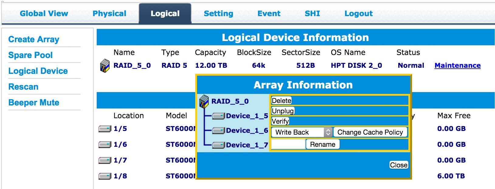
If you click the Maintenance link a small dialog box called Array Information should appear. Within this dialog box there are four functions available: Delete, Unplug, Verify, and Rename. They are described below.
A. Delete – this option deletes the logical disk array and all of its data.
B. Unplug – this option is the same as unmounting a disk from your operating system before physically disconnecting it. You should do this first if you need to physically remove a disk from your enclosure.
C. Verify – when the array in question is a RAID 1, RAID 5, RAID 10, or RAID 50, this option rebuilds the entire array to ensure its integrity. No data is lost during this process, but it can take many hours to complete, depending on the size of the array. Typically arrays are rebuilt at a rate of about 6 hours per terabyte (1TB).
D. Rename – use this feature to rename the existing RAID array.
Rescan
If you click Rescan the RAID Management application will recheck the devices connected to the system to check for newly mounted RAID volumes and new spare drives. Occasionally you may need to use this feature to update the Logical Device screen or other screens after you have performed an action within the RAID Management application, such as creating a new array.
Beeper Mute
This feature will temporarily turn off the alarm on your MAXPower card.
Spare Pool
The Spare Pool screen will show you which drives remain available for use as spares, should one of the drives in your RAID 1, RAID 5, RAID 10 or RAID 50 array fail. Simply select the disk(s) you want to include and click the Add Spare button. When you do so, the drive will automatically be made available any time a drive failure is detected.

2.4.4 Setting Raid Management Options
The Setting panel houses optional features that can enhance the efficiency of the array and disk management process. Each option shown in the screenshot is described below. Note: the settings shown are the defaults for OS X.
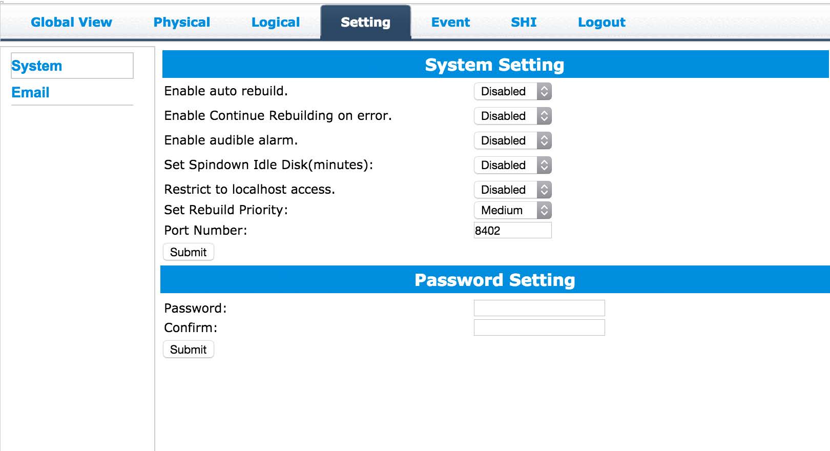
Enable Auto Rebuild
When this option is enabled the Auto Rebuild option allows the RAID controller to use any matching unformatted drive when rebuilding a failed array, regardless of whether that drive is designated in the Spare Pool, which is discussed in Section 2.4.3.
Enable Continue Rebuilding On Error
When this option is enabled, the RAID controller will attempt to continue rebuilding a failed array, even if it is encountering read errors when accessing one or more disks in the array.
Enable Audible Alarm
When this option is enabled, the audible alarm will sound on the RAID controller card if certain errors or hardware conditions are encountered (e.g. removing a physical disk from the array during usage or disconnecting the enclosure from the mini-SAS controller).
Set Spindown Idle Disk (minutes)
This option allows disks in the array to be spun down when there is no disk activity. The timer can be set to as little as 10 minutes and as much as 240 minutes before spinning the disks down.
Restrict To Localhost Access
This option ensures that the RAID Management application can only be accessed by a local machine. Remote access will be denied.
Set Rebuild Priority
This provides a range of priority settings which determine the degree to which system resources are dedicated to the rebuilding of an array. Lowest Priority allows all other system processes to take priority, while Highest Priority gives the rebuild process top priority.
Port Number
This option sets the listening port number. 7402 is the default for PCs, 8402 is the default for Macs. Any available port can be used.
2.4.5 Events Log
The Event panel shows a listing of array and disk activities that have been logged by the RAID Manager application. There are three general types of events, each marked by a specific icon. These icons are shown in screenshot and described below.
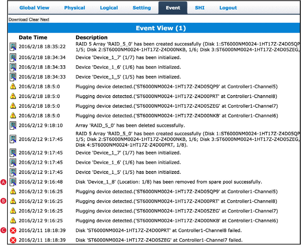
A. The event log icon Indicates general information and occurrences.
B. The yellow icon denoted minor occurrences and issues that may require attention. These include things like a change to the hardware that is detected and minor issues such as inconsistent data that can be easily fixed by a rebuild.
C. The red icon provides a warning about major occurrences and problems, such as failed drives and improper disconnection of drives from an array.
2.4.6 Storage Health Inspector (shi)
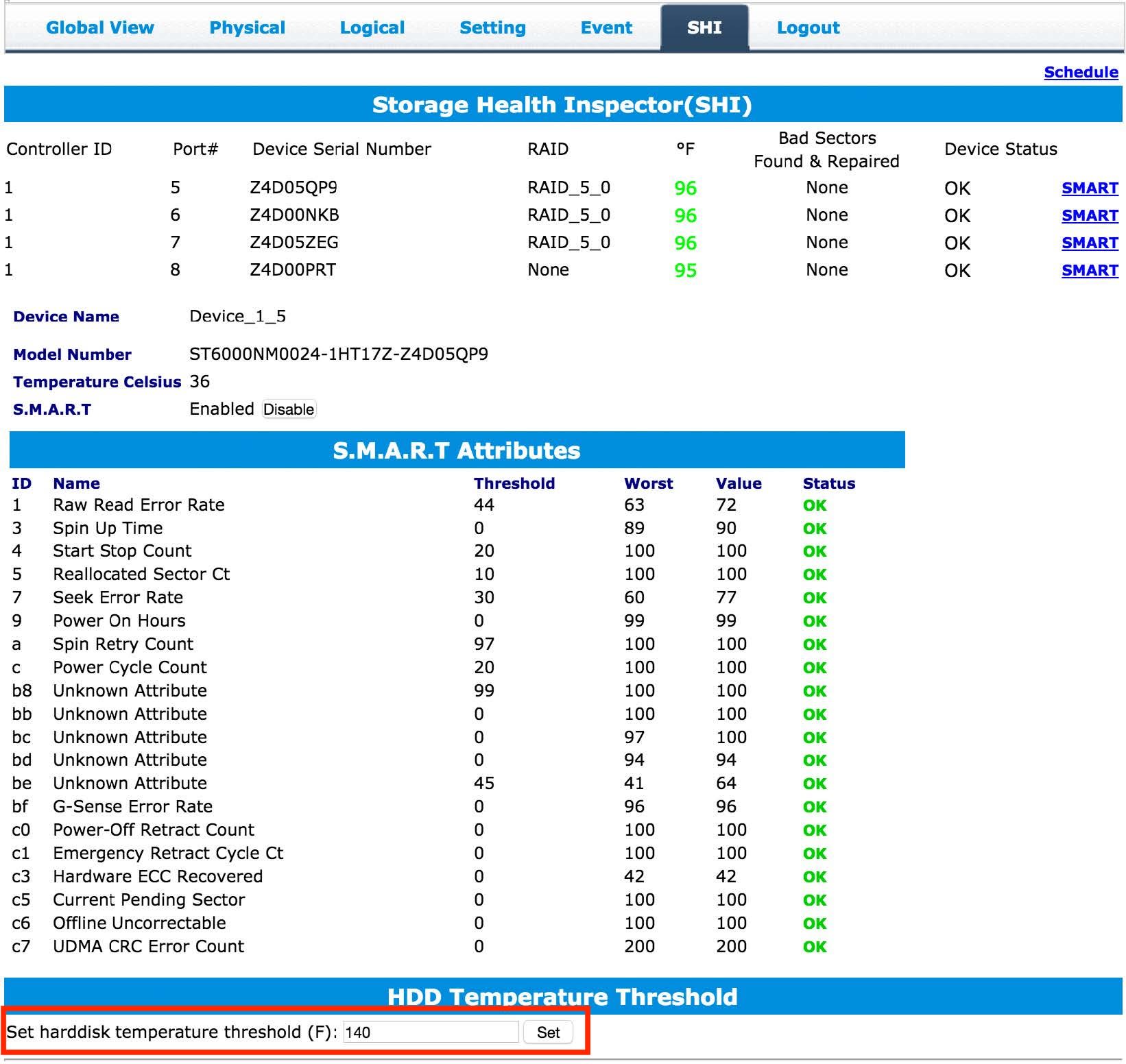
The Storage Health Inspector periodically inspects the physical disks included in the array. Any problems will be logged on the Event screen described in Section 2.4.5. This helps to identify problems before they become more serious, allowing you to update the array as necessary. Among the items the inspector keeps track of are Self-Monitoring, Analysis, and Reporting Technology (S.M.A.R.T.) attributes within each drive; monitoring these items can help avoid a catastrophic disk failure in some instances. To view the S.M.A.R.T status attributes of an attached drive, click on “SMART” to expand the attributes for viewing. The screenshot below shows the attributes for Device_1_5 in the array. NOTE: not all enclosure types support SMART data.
The SHI panel also provides an operating temperature threshold for each disk (shown in red), warning you if the threshold is exceeded.
Support Resources
3.1 Troubleshooting
If a connected storage device is not recognized after connecting it:
First, try disconnecting the device from the MAXPower eSATA 6G-4e card and then connecting it again. If the device is still not recognized, keep the storage device turned on and connected to the MAXPower eSATA 6G-4e card and restart your machine. Please contact Technical Support for further assistance.
If the MAXPower eSATA 6G-4e card is not being recognized by the computer:
First, make sure the card is seated completely in the PCIe slot by reviewing Section 2.2 Hardware Installation. If the card is still not recognized, try installing the card into a different PCIe slot. If the card is still not recognized, please contact Technical Support for assistance.
Does the MAXPower Mini-SAS 6G card support booting?
Booting from the MAXPower eSATA 6G-4e card is only supported on Mac with the appropriate EFI firmware update. To find this update go to www.newertech.com/support#data and look for the item called “MAXPower PCIe 4-Port eSATA 6G RAID Controller Card Mac EFI”, then download it and install it according to the instructions in the included Read Me file.
On PCs, BIOS booting to RAID is supported.
Why does the card alarm sound when I disconnect the eSATA cable?
The audible alarm on the card is disabled by default, but if it is enabled you must follow a different procedure for physically disconnecting drives from the card. Even though you ejected the drive from the desktop, you must still “unplug” it from the RAID Management application interface. Log into the RAID Management application and click on the “Maintenance” link for the array you wish to disconnect and click on the “Unplug” button. Now the drives are ready to be physically unplugged from the RAID card.
There are two PCIe cards installed that use the same localhost and now I can’t access either card, what do I do?
Remove one of the cards in order to gain access to the RAID Management application. Navigate to the Setting panel (see Section 2.4.4) and change the Listening Port from 7402 or 8402 to another 74xx or 84xx number, respectively. You should now be able to access both cards — the MAXPower card on the default port and the second card on the newly assigned port.
What happens if I connect a drive that is already formatted?
The MAXPower RAID controller has an automatic pass-through (or “Legacy”) feature that will pass any connected drive to the OS without needing to initialize it via the RAID Manager. The exception to this rule is when a drive or drives have been initialized via the RAID Management application, for use in a RAID array or as a hot spare. These disks will appear in the RAID Management application with the letter L (to denote Legacy status) over the icon.
3.2 About Data Backup
To ensure that your files are protected and to prevent data loss, we strongly suggest that you keep two copies of your data: one copy on the JBOD or RAID array, and a second copy on another storage medium, such as an optical backup, or on a second external storage unit. Any data loss or corruption while using the MAXPower RAID controller is the sole responsibility of the user, and under no circumstances may NewerTech, its parents, partners, and affiliates be held liable for loss of the use of data including compensation of any kind or recovery of the data.
Changes
The material in this document is for information purposes only and subject to change without notice. While reasonable efforts have been made in the preparation of this document to assure its accuracy, Newer Technology, Inc., its parent, affiliates, officers, employees, and agents assume no liability resulting from errors or omissions in this document, or from the use of the information contained herein. Newer Technology, Inc. reserves the right to make changes or revisions in the product design or the product manual without reservation and without obligation to notify any person of such revisions and changes.
FCC Statement
Warning! Modifications not authorized by the manufacturer may void the user’s authority to operate this device.
NOTE: This equipment has been tested and found to comply with the limits for a Class A digital device, pursuant to Part 15 of the FCC Rules. These limits are designed to provide reasonable protection against harmful interference when the equipment is operated in a commercial environment. This equipment generates, uses, and can radiate radio frequency energy and, if not installed and used in accordance with the instruction manual, may cause harmful interference with radio communications. Operation of this equipment in a residential area is likely to cause harmful interference, in which case the user will be required to correct the interference at his own expense.
NOTE: This equipment has been tested and found to comply with the limits for a Class B digital device, pursuant to Part 15 of the FCC Rules. These limits are designed to provide reasonable protection against harmful interference in a residential installation. This equipment generates, uses and can radiate radio frequency energy and, if not installed and used in accordance with the instructions, may cause harmful interference to radio communications. However, there is no guarantee that interference will not occur in a particular installation. If this equipment does cause harmful interference with radio or television reception, which can be determined by turning the equipment off and on, the user is encouraged to try to correct the interference by one or more of the following measures:
- Reorient or relocate the receiving antenna.
- Increase the separation between the equipment and receiver.
- Connect the equipment to an outlet on a circuit different from that to which the receiver is connected.
Health And Safety Precautions
- Read this user guide carefully and follow the correct procedures when setting up the device.
- Use proper anti-static precautions while performing the installation of this product. Failure to do so can cause damage to the device and/or the computer or enclosure where it is installed.
- Do not attempt to disassemble or modify the device. To avoid any risk of electrical shock, fire, short-circuiting or dangerous emissions, never insert any metallic object into the device. If it appears to be malfunctioning, contact Newer Technology technical support.
- Never expose your device to rain, or use it near water or in damp or wet conditions. Never place objects containing liquids on the drive, as they may spill into its openings. Doing so increases the risk of electrical shock, short-circuiting, fire or personal injury.
General Use Precautions
- To avoid damage, do not expose the device to temperatures outside the range of 5° C to 50° C (41° F to 122° F).
- Do not place heavy objects on top of the device.
- Protect your device from excessive exposure to dust during use or storage. Dust can build up inside the device, increasing the risk of damage or malfunction.
- For up-to-date product and warranty information, please visit the product web page.
Copyright and Trademarks
No part of this publication may be reproduced, stored in a retrieval system, or transmitted in any form or by any means, electronic, mechanical, photocopying, recording or otherwise, without the prior written consent of Newer Technology, Inc.
© 2018 Other World Computing, Inc. All rights reserved.
NewerTech and the NewerTech logo are trademarks of New Concepts Development Corporation, registered in the U.S. and/or othercountries. The n boomerang logo is a trademark of New Concepts Development Corporation. Apple, Mac, and OS X are trademarks of Apple Inc., registered in the U.S. and other countries. Microsoft and Windows are either registered trademarks or trademarks of Microsoft Corporation in the United States and/or other countries. Other marks may be the trademark or registered trademark property of their owners.
Free Support Chat
Our free award-winning support team is ready to answer all of your questions. Technical support is available Monday - Friday: 9AM - 6PM. Customer Support & Sales is available Monday - Friday: 9AM - 6PM. Support is unavailable on U.S. Federal holidays. Talk to a human today.


 1-800-275-4576