Mercury Accelsior Pro Q
Installation Guide
Introduction
1.1 Minimum System Requirements
1.1.1 Apple Mac Requirements
- Mac Pro 3,1 MacPro4,1 MacPro5,1
- PCIe 2.0 x16 slot recommended for best performance.
- Driver Required
- OS X 10.9-10.11.6
- macOS 10.12 or later
1.1.2 PC Requirements
- PC with a x8 or x16 slot
- PCIe 2.0 or higher recommended
- Driver Required (Windows 7 or later)
Important: The Accelsior Pro Q cannot be used as a system drive or boot-drive on either Mac or PC. The driver can be downloaded at: here
1.1.3 PCIe Chassis Requirements
- Compatible with most Thunderbolt™ PCIe chassis
- Not compatible with OWC Mercury Helios 3
1.2 Package Contents
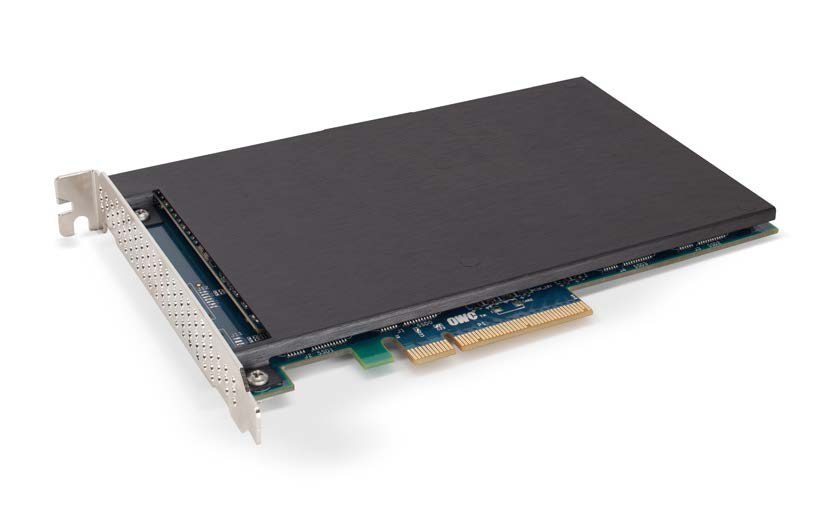
- OWC Mercury Accelsior Pro Q SSD
- Power Splitter Cable
1.3 About This Manual
The images and descriptions may vary slightly between this manual and the unit shipped. Functions and features may change depending on the firmware version. The latest product details and warranty information can be found on the product web page. OWC’s Limited Warranty is not transferable and subject to limitations.
Device Setup
Attention: Observe Precautions For Handling Electrostatic Sensitive Devices
Your computer is a static-sensitive device. It is susceptible to invisible damage if not protected during installation. We recommend proper grounding by using a grounding strap. Make sure to work in a clean, static-free area, and avoid wearing clothing that retains static charges.
2.1 Installation: Mac Pro 2009–2012
Before proceeding with the installation steps below, shut down your Mac Pro, disconnect the power cable and all connected peripherals.
1. Lift the latch on the back of the Mac Pro (not shown) and then remove the side-cover. Once removed you should see a view of the Mac Pro similar to the one below.
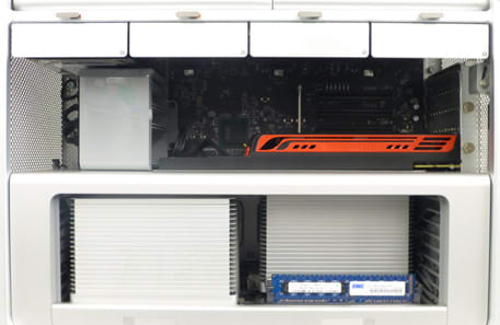
2. To create more room, remove the two drive trays on the left. If you find it difficult to access the items required in subsequent steps, remove the remaining two trays.
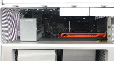
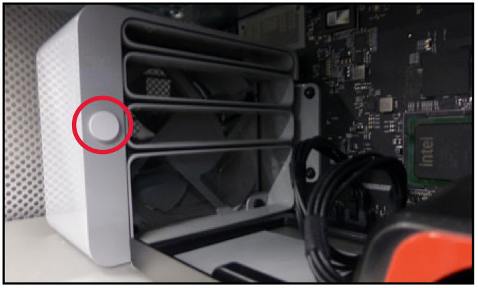
3. Press and hold the circular, grey button on the right edge of the fan assembly, then gently push the outer part of the assembly towards the front of the Mac Pro. This will allow you to remove full length GPUs. Note the numbered grooves that are revealed (not shown); these correspond to each PCIe slot on the logic board.
4. If your GPU (graphics card) has a power cable extending from the back of it, carefully disconnect it from the GPU. The appearance of your GPU may vary.
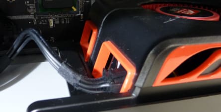
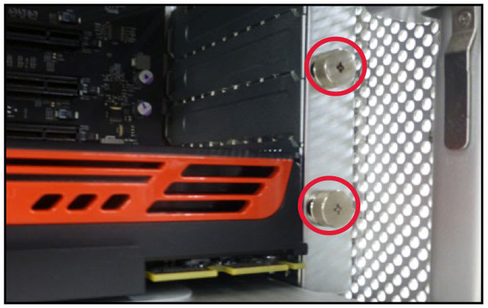
5. Loosen the two thumbscrews on the PCIe slot cover plate at the back of the Mac Pro, then remove the plate. You may need to use a short Phillips screwdriver.
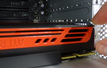
6. Carefully remove the GPU from its PCIe slot. If the GPU is also slotted into the fan assembly noted in Step 3, slide the left edge of the card toward you first, in order to pull the card out of the case. Do not attempt to force the card out of the case if it feels stuck.
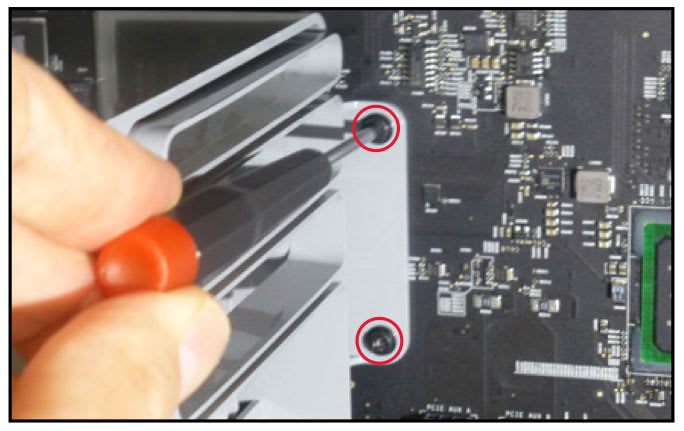
7. Loosen the two Phillips screws on the fan housing (shown in red), then use your fingers to make the final few turns and remove the screws. This will help ensure you don’t drop them inside the machine, as they can be difficult to retrieve.
8. Pull the entire fan assembly straight out. If it catches on the cut-outs (shown below-right) you may have to tilt it or lift upward slightly as you pull.
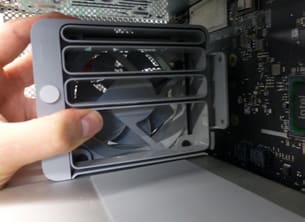
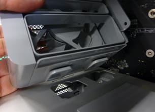
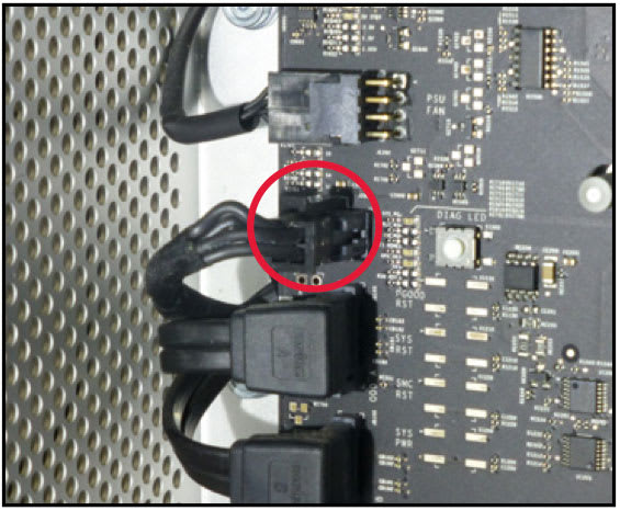
9. Hold down the clip on the top of the 4-pin power cable (shown in red) and gently pull the plug toward you to disconnect it from the logic board’s power port.
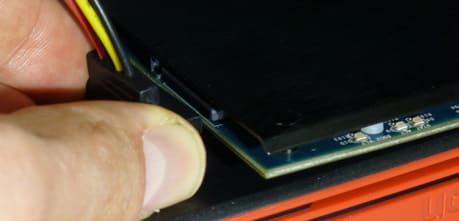
10. Connect the female, 4-pin connector on the short end of the included power splitter cable (below left), to the cable you disconnected in Step 9. You may need to rotate the connectors slightly in order be sure that the clip on the 4-pin power cable (yellow arrow, below-right) is oriented so that it slides over the triangular latch on the splitter cable’s 4-pin connector. It should snap into place.

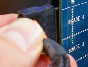
11. Connect the male 4-pin connector on the power splitter cable to the power port on the logic board (shown in Step 9). Make sure the clip on the cable is oriented so that is rests on the top side of the power port. It should snap into place.
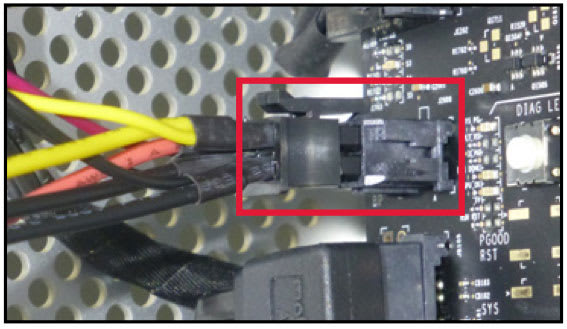
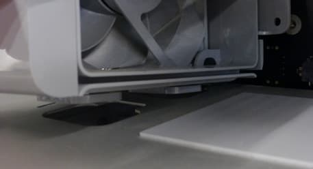
12. Reseat the fan assembly into the two slots on the metal casing (shown below) and carefully slide it all the way to the logic board. Refasten the screws removed in Step 7.
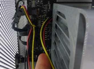
13. Thread the cable you connected in Steps 10 and 11 over and around the back of the fan assembly, as shown below. Be careful not to crimp the cable.
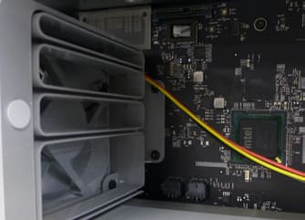
14. Carefully reseat the GPU into the PCIe slot, then reconnect its power cable. Note: If you have a full-length GPU, make sure the outer part of the fan assembly that you slid to the left in Step 3, is still to the left so that you can slide the rear portion of the GPU into the case first.
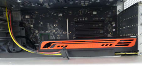
15. Remove the slot cover that corresponds to the open 16x PCIe slot, then carefully install the Accelsior Pro Q into that slot. Note: this SSD will also work with an available PCIe 2.0 x4 slot, but at reduced speeds.
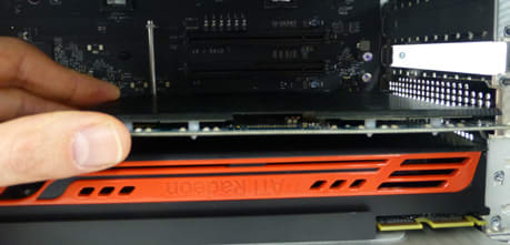
16. Connect the long end of the included power cable to the back of the Mercury Accelsior Pro Q. Make sure the cabling extends upward.
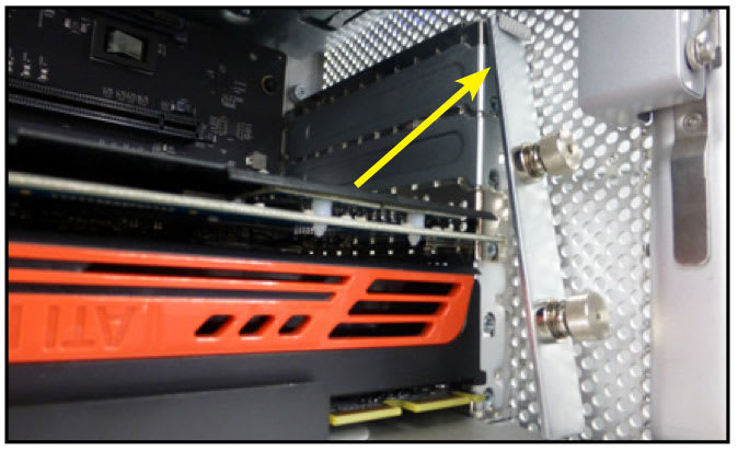
17. Reseat the slot cover plate that you removed in Step 4 and secure the GPU and Accelsior Pro Q brackets to the back of the Mac Pro using the plate’s thumbscrews. You may need to angle the top in first (shown at rest on the PCIe mezzanine below), then nudge the bottom edge straight back until it snaps into place. It is a tight fit by design.
18. Reseat all drive trays that were removed during the installation. Then re-seat the side cover on the Mac Pro and secure it using the latch on the back of the computer. The installation process is now complete. Proceed to Section 3.1 —Driver Information
Attention: Observe Precautions For Handling Electrostatic Sensitive Devices
Your computer is a static-sensitive device. It is susceptible to invisible damage if not protected during installation. We recommend proper grounding by using a grounding strap. Make sure to work in a clean, static-free area, and avoid wearing clothing that retains static charges.
2.2 Installation: Mac Pro 2008
Before proceeding with the installation steps below, shut down your Mac Pro, disconnect the power cable and all connected peripherals.
1. Lift the latch on the back of the Mac Pro then remove the side-cover and set it aside.
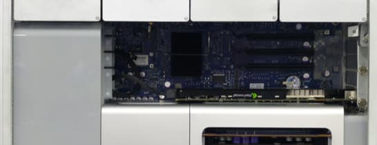
2. Remove the two drive trays on the left so there is more room to work inside the case. If you need more room in subsequent steps, you can remove the two remaining drive trays.
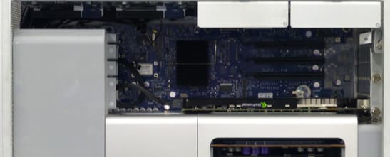
3. Loosen the two thumbscrews on the PCIe slot cover plate , then remove the plate. You may need to use a short Phillips screwdriver.
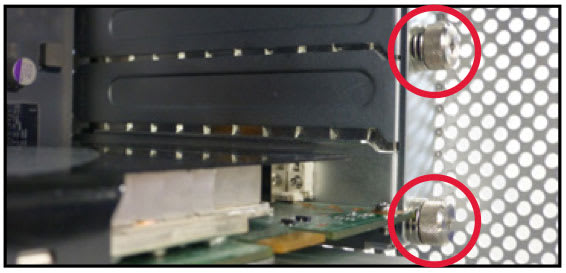
4. If there is a power cable attached to the back of your GPU (graphics card), carefully detach it before proceeding to the next step.
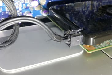
5. Carefully remove the GPU from its PCIe slot. Note the other PCIe cover plates on the back of the Mac Pro are removed in this photo; this is optional at this stage.
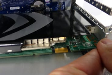
6. Remove the CPU heat sink cover. It is attached with magnets; you may need to lift up from the edge closest to the logic board first, then carefully wiggle the cover until it comes loose, at which point you can pull it out towards you to remove it.
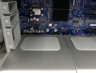
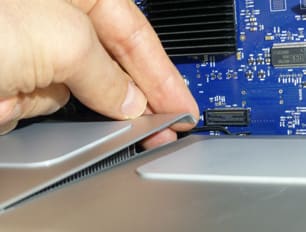
7. Loosen and remove the silver colored Phillips screw from the bottom-right edge of the fan assembly. Take care not to drop the screw once it is loose. We recommend a magnetic-tipped screwdriver if you have one.
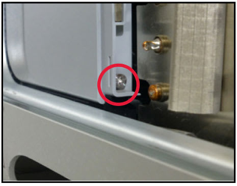
8. Loosen and remove the black Phillips screw (circled in red) from the top of the fan assembly. Again take care not to drop the screw; you may want to perform the last couple turns with your fingers so that you can have a grip on it when it comes loose.
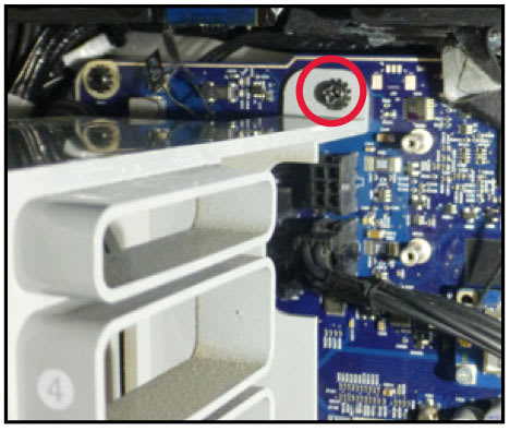
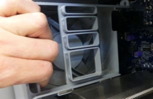
9. Place your hand on the upper-left inside region of the fan assembly and gently pull it towards you. You may need to jiggle the assembly slightly for it to come loose.
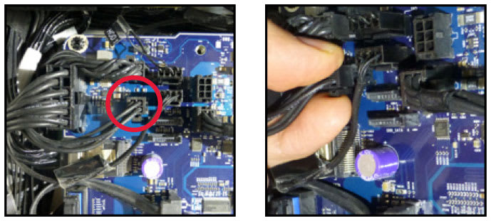
10. Disconnect the 4-pin power cable from the power port near the top-left corner of the logic board (it may be marked “J1B1” to the left of the port).
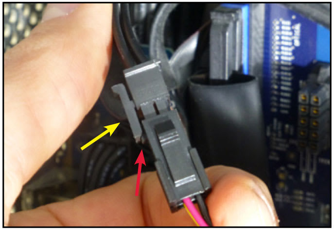
11. Connect the female, 4-pin connector on the short end of the included power cable, to the cable you disconnected in Step 10. You may need to rotate the connectors slightly to be sure the clip on the 4-pin power cable is oriented so that it rests over the triangular latch on the included power cable’s 4-pin connector. It should snap into place.
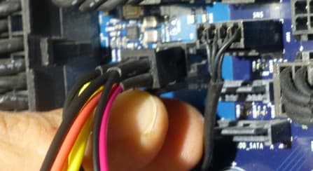
12. Plug the other connector on the included cable into the logic board’s power port referenced in Step 10. Note here that the clip should be oriented toward the bottom of the power port, so that it slides over the triangular latch and snaps into place.
13. To avoid pinning the cable against the logic board, tuck the slack on the short end of the cable to the left side if you can (red arrow, below-left), then slide the fan assembly back into the enclosure part way. Make sure to align the grooves on the bottom of the assembly to the slot on the bottom of the computer case, and make sure the long end of the included power cable is threaded behind the fan assembly as shown below.
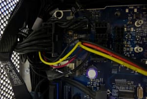
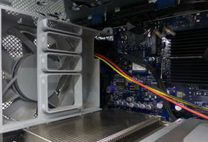
14. Carefully press the assembly all the way back to the logic board. With one hand apply gentle pressure on the fan assembly to make sure it is contacting the logic board, then with the other hand re-affix the black Phillips screw that you removed in Step 8.
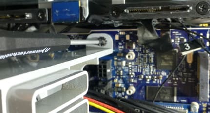
15. Next re-affix the silver Phillips screw you removed in Step 7. Before you perform this step, it may help to remove the lower RAM riser card, in order to get a better angle with the screwdriver. The riser looks like a blue plate with two circles cut out on the corners.
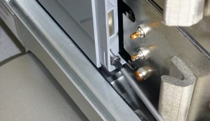
16. Re-attach the CPU heat sink cover you removed in Step 6. First, slot the bottom edge into the open space, then gently nudge the top edge down until it snaps into place (the connectors are magnetic).
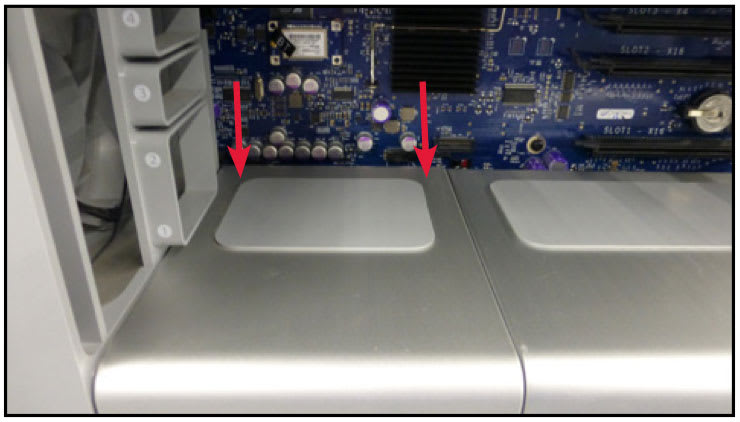
17. Make sure the plug for the power splitter cable is not sitting in a position where it might interfere with the PCIe slots. Carefully reseat your GPU, then reconnect the power cable to your GPU, if applicable.
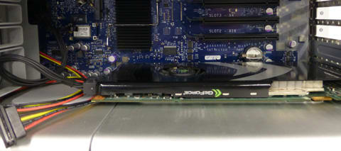
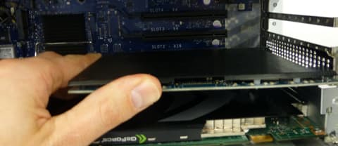
18. Remove the rear slot cover that corresponds to the open 16x PCIe slot, then carefully install the Accelsior Pro Q into that slot. Note: this SSD should also work in one of the other available PCIe slots, but at substantially reduced speeds.
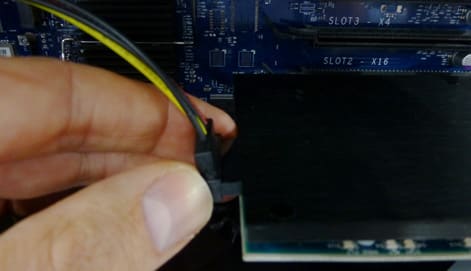
19. Connect the long end of the power splitter cable to the back of the Accelsior Pro Q. Make sure that the key on the plug is matched to the key on the drive, resulting in the power cable extending upward.
20. Re-seat the plate that you removed in Step 3, secure the GPU and Accelsior Pro Q using the thumbscrews. You may need to tuck the cable slack behind the fan assembly, depending on the amount of space and number of PCIe cards installed in your Mac Pro.
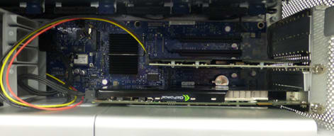
21. Reseat all drive trays that were removed during the installation. Then, re-seat the side cover on the Mac Pro and secure it using the latch on the back of the computer. The installation process is now complete.
2.3 Installation: PC Logic Board (ATX)
Make sure your PC is shut down and disconnected from its power source and from external peripherals.
1. Remove the PC case. Locate an available PCIe 2.0 or PCIe 3.0 slot marked ‘x8’ or ‘x16’.
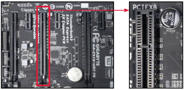
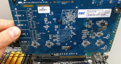
2. Align the Mercury Accelsior Pro Q to the notches on the PCIe slot as shown below, then gently press the Accelsior Pro Q downward until it snaps into place.
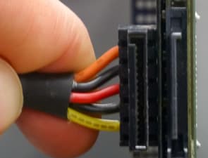
3. Connect a SATA power cable from the power supply into the back of the Accelsior Pro Q.
4. Close the PC case, reconnect the power and peripherals and power on the PC. The Accelsior should be recognized automatically and Windows should prompt you to download a driver.
Support Resources
3.1 Driver Information
In order to use the Mercury Accelsior Pro Q as designed, you need to first install a driver for your computer. A PC should detect the Accelsior Pro Q automatically and suggest the correct driver for download. If you installed this device in a Mac Pro, please visit the URL below to download and install your driver, before formatting and using the drive (see below).
Mac users: www.owcdigital.com/support/software-drivers
3.2 Formatting
Once you have installed your OWC Mercury Accelsior Pro Q driver successfully and have restarted your computer, please visit this page to learn about formatting options specific to your system. here
3.3 Troubleshooting
If the Accelsior Pro Q is not recognized by your operating system even after installing the driver, it is a good idea to shut down, disconnect the power cable to the computer and any external peripherals, open the case and attempt to reseat the card as described earlier in this manual. You will also want to verify that the power cable is properly connected to the back of the SSD.
If you verify that the drive is properly seated in the PCIe slot and the power cable is also properly connected to the back of the drive, for more information on contacting technical support.
3.4 About Data Backup
To ensure that your files are protected and to prevent data loss, we strongly suggest you keep two copies of your data: one copy on your OWC Mercury Accelsior Pro Q and a second copy on another internal drive or other storage medium, such as an optical backup or an external storage unit. Any data loss or corruption while using the Accelsior Pro Q is the sole responsibility of the user, and under no circumstance may OWC, its parent, partners, affiliates, officers, employees, or agents be held liable for compensation or the recovery of any lost data.
Changes
The material in this document is for information purposes only and subject to change without notice. While reasonable efforts have been made in the preparation of this document to assure its accuracy, OWC, its parent, affiliates, officers, employees, and agents assume no liability resulting from errors or omissions in this document, or from the use of the information contained herein. OWC reserves the right to make changes or revisions in the product design or the product manual without reservation and without obligation to notify any person of such revisions and changes.
FCC Statement
Warning! Modifications not authorized by the manufacturer may void the user’s authority to operate this device.
NOTE: This equipment has been tested and found to comply with the limits for a Class A digital device, pursuant to Part 15 of the FCC Rules. These limits are designed to provide reasonable protection against harmful interference when the equipment is operated in a commercial environment. This equipment generates, uses, and can radiate radio frequency energy and, if not installed and used in accordance with the instruction manual, may cause harmful interference with radio communications. Operation of this equipment in a residential area is likely to cause harmful interference, in which case the user will be required to correct the interference at his own expense.
NOTE: This equipment has been tested and found to comply with the limits for a Class B digital device, pursuant to Part 15 of the FCC Rules. These limits are designed to provide reasonable protection against harmful interference in a residential installation. This equipment generates, uses and can radiate radio frequency energy and, if not installed and used in accordance with the instructions, may cause harmful interference to radio communications. However, there is no guarantee that interference will not occur in a particular installation. If this equipment does cause harmful interference with radio or television reception, which can be determined by turning the equipment off and on, the user is encouraged to try to correct the interference by one or more of the following measures:
- Reorient or relocate the receiving antenna.
- Increase the separation between the equipment and receiver.
- Connect the equipment to an outlet on a circuit different from that to which the receiver is connected.
Health And Safety Precautions
- Do not perform maintenance or installations to your computer while it is plugged into a power source.
- Use proper anti-static precautions while performing the installation. Failure to do so can cause damage to your drive.
- Read this user guide carefully and follow the correct procedures when setting up the device.
- Do not attempt to disassemble or modify the device. To avoid any risk of electrical shock, fire, short-circuiting or dangerous emissions, never insert any metallic object into the device. If it appears to be malfunctioning, contact technical support.
- Never expose your device to rain, or use it near water or in damp or wet conditions. Never place objects containing liquids on the drive, as they may spill into its openings. Doing so increases the risk of electrical shock, short-circuiting, fire or personal injury.
General Use Precautions
- To avoid damage, do not expose the device to temperatures outside the range of 5° C to 40° C (41° F to 104° F).
- Protect your device from excessive exposure to dust during use or storage. Dust can build up inside the device, increasing the risk of damage or malfunction.
- For up-to-date product and warranty information, please visit the product web page.
Copyrights and Trademarks
No part of this publication may be reproduced, stored in a retrieval system, or transmitted in any form or by any means, electronic, mechanical, photocopying, recording or otherwise, without the prior written consent of OWC.
© 2017 OWC. All rights reserved.
OWC and Mercury Accelsior are trademarks of New Concepts Development Corporation, registered in the U.S. Patent and Trademark Office and/or in Canada. Pro Q and The OWC logo are trademarks of New Concepts Development Corporation. Apple, Mac, Mac Pro, macOS, and OS X are trademarks of Apple Inc., registered in the United States and other countries. Thunderbolt and the Thunderbolt logo are trademarks of Intel Corporation or its subsidiaries in the U.S. and/or other countries. Microsoft and Windows are either registered trademarks or trademarks of Microsoft Corporation in the United States and/or other countries. Other marks may be the trademark or registered trademark property of their owners.
Free Support Chat
Our free award-winning support team is ready to answer all of your questions. Technical support is available Monday - Friday: 9AM - 6PM. Customer Support & Sales is available Monday - Friday: 8AM - 8PM. Support is unavailable on U.S. Federal holidays. Talk to a human today.


 1-800-275-4576