Multi-Mount
Assembly Manual for 2006-2008 Mac Pro Kits
Introduction
1.1 Hardware Requirements
1.1.1 Compatible Systems
- Any 2006 - 2008 Mac Pro system
1.1.2 Drive Requirements
- Supports any 3.5 inch or 2.5 inch SATA drive.
1.1.3 Tool Requirements
- Magnetic-tipped Phillips screwdrivers (sizes: #1, #2)
- Needlenose pliers
1.2 Package Contents
- 4 Pin Power to SATA Power Y Cable or single SATA Power Cable
- SATA cable – 2 straight connectors
- SATA cable – 1 straight connector, 1 angled connector (not shown)
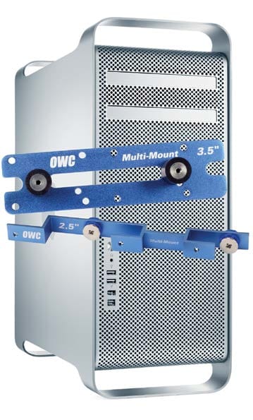
- OWC Multi-Mount 3.5” Drive Bracket (2 pieces)
- OWC Multi-Mount 2.5” Drive Bracket (4 pieces, 2 required per drive)
- Screws for 3.5” Bracket - Coarse Thread (16 pieces)
- Screws for 2.5” Bracket - Fine Thread (12 pieces)
NOTE: Depending on type of Multi-Mount kit you purchased, contents may differ from the contents listed above. Please check your invoice for exact contents.
1.3 About This Manual
The OWC Multi-Mount brackets are sold both individually and as sets. This manual details both types of brackets. The images included in this manual may vary slightly in appearance from the items you received, including the cables. Please visit the product web page for the most recent product information.
Computer Setup
2.1 Mac Pro 2006-2007 (Disassembly)
1. Remove the cover from the side of the Mac Pro.
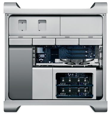
2. Locate the memory riser-cards near the lower-right corner of the case.
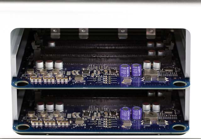
3. Remove the two riser cards, exposing the Phillips screws shown below.
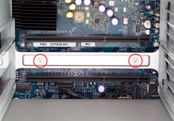
4. Remove the two Phillips screws.
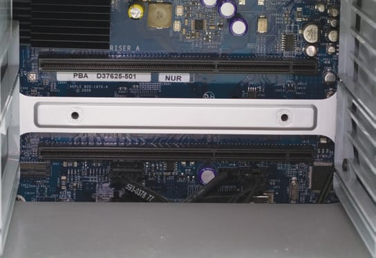
5. At the bottom of the memory bay there are two Phillips screws, shown below. Use a Phillips screwdriver to remove them.

IMPORTANT: in many cases these specific screws were improperly installed. Instead of using Loctite on the screw standoff, Apple used Loctite on the screws themselves. For those cases, if you attempt to remove the screws, the standoffs themselves will turn instead of the screws. If this is applicable to your Mac Pro, you may need to use a very thin pair of needle nose pliers or a thin, flat-blade screwdriver to hold the standoff tight while you loosen the Phillips screws.
6. Make sure the latch on the back of the Mac Pro is open, then remove all four of the drive sleds and set them aside.
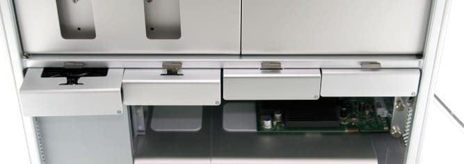
7. Look inside the PCI Express (PCIe) bay at the top right of the Mac Pro. You’ll need to remove items from this location next.
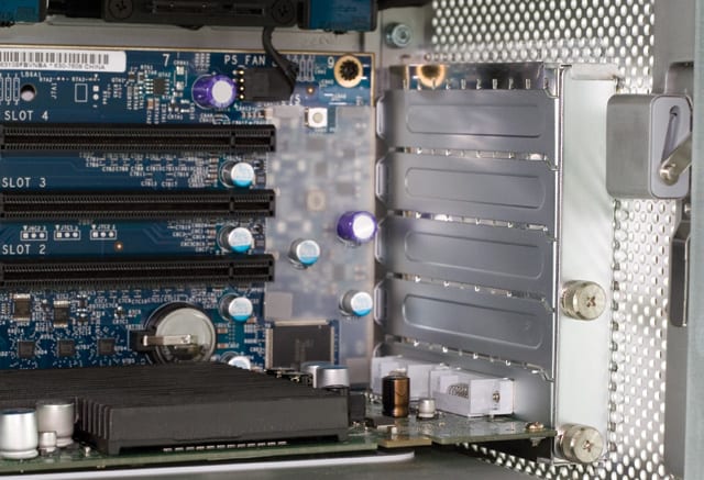
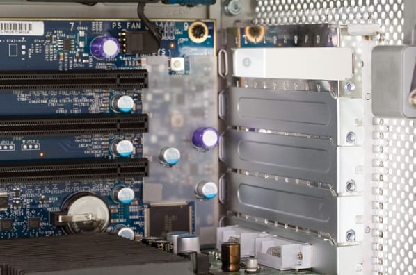
8. Using a Phillips screwdriver or your fingers, loosen the thumbscrews shown below then remove the plate that holds the PCIe slot covers in place. Slide the plate down slightly before pulling it towards you, then set it aside.
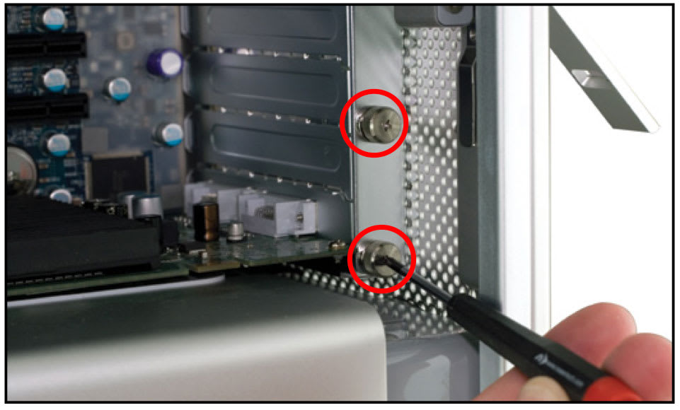
9. Remove the top PCIe slot cover from the top slot, as shown below. Set the plate cover aside; you will need it later.
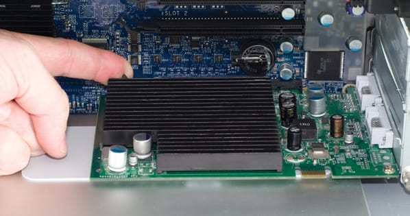
10. Remove your Graphics Processing Unit (GPU). It may look similar to the green PCIe card shown below. At the rear of the PCI Express slot there is a small plastic tab -- lift it to unlock the GPU. While doing this, nudge the card toward you to loosen its connection from the PCIe slot. Once the GPU is loose, carefully remove the card by pulling it straight out of the case. Set the card aside, placing it in a static-free bag if you have one.
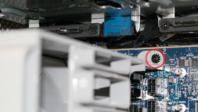
11. Immediately to the left of the PCI slots, at the top of the logic board, you will see a black screw the connects the fan assembly to the board (circled in red below). Use a Phillips screwdriver to remove it.
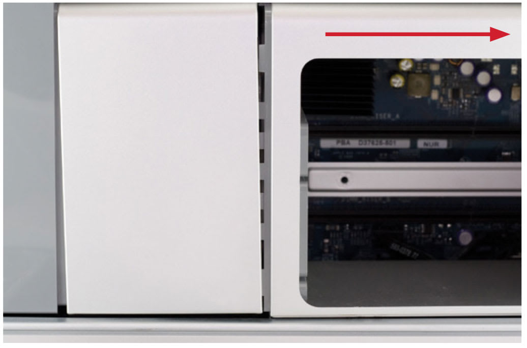
12. Gently slide the memory bay to the right, towards the back of the computer. You’ll be able to gently shake it and it will pop loose and move just enough to expose a gap between the processor cover and the memory bay, as shown below.
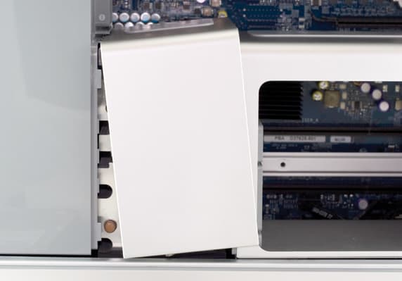
13. Pull outward on the bottom of the processor cover (the metal component immediately to the left of the memory bay) and carefully remove it. It tilts upward and to the right, as shown. The connection to the fan assembly may be tight.
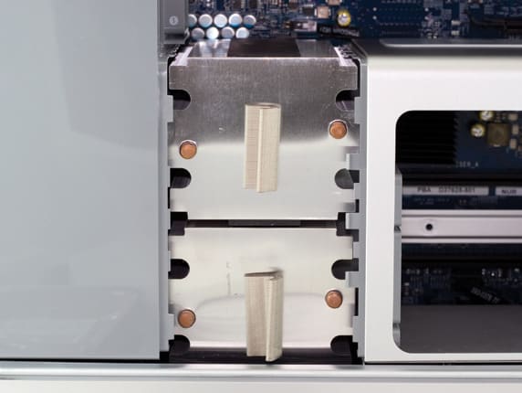
14. A view of the processor heatsinks with the cover removed.
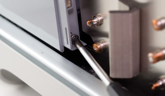
15. Some later model Mac Pro systems, especially 8-Core models, have a hidden Phillips screw located a the base of the fan assembly (shown below). Unscrew it and carefully remove it. If possible, use a magnetic-tipped driver to avoid dropping the screw into the bottom of the case.
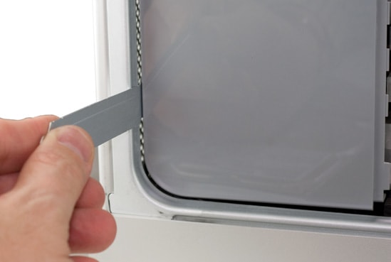
16. Take the L-shaped PCIe slot cover you removed earlier. Starting at the top of the fan shroud, work the short end of the cover into the gap at the front of the Mac Pro. Once the bracket is inserted, use it like a hook to help dislodge the fan assembly from the case. Place the bracket at the bottom-left, then start putting gentle force on the bracket, pulling on it.
17. Gently ease the entire fan assembly out of the case. You may need to use a slight side-to-side motion as you pull the assembly towards you.
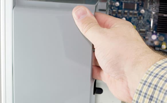
This completes the disassembly process for 2006-2007 Mac Pros. Please proceed to Section 2.3 Cable Installation.
2.2 Mac Pro 2008 (Disassembly)
1. Remove the cover from the side of the Mac Pro.
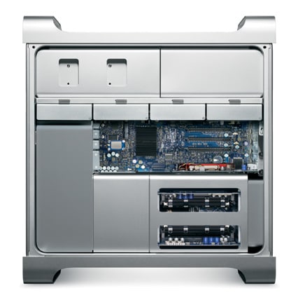
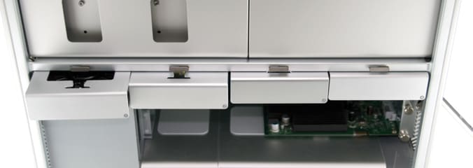
2. Make sure the latch on the back of the Mac Pro is open, then remove all four of the drive sleds and set them aside.
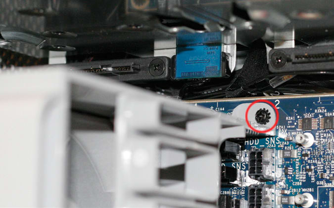
3. Immediately to the left of the PCI slots, at the top of the logic board, you will see a black screw the connects the fan assembly to the board. Use a Phillips screwdriver to remove it.
4. Remove the CPU cover by pulling on it. Note that it is held in place by magnets.
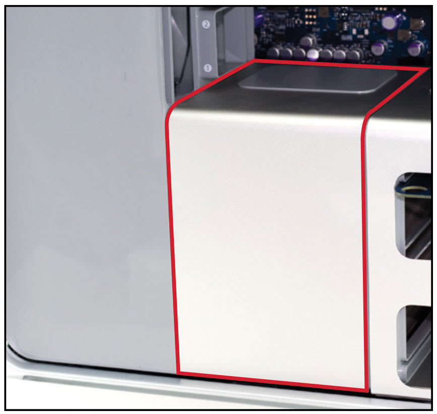
5. Unscrew the Phillips screw shown below from the base of the fan assembly, then remove it. Take care not to drop the screw into the bottom of the case. Use a magnetic-tipped driver if one is available.
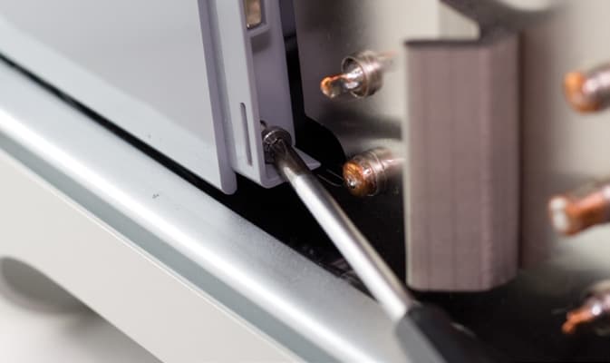
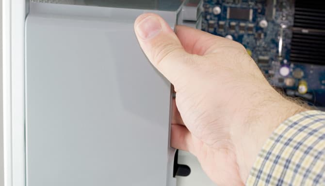
6. Gently ease the entire fan assembly out of the case. You may need to use a slight side-to-side motion as you pull the assembly towards you.
2.3 Cable Installation
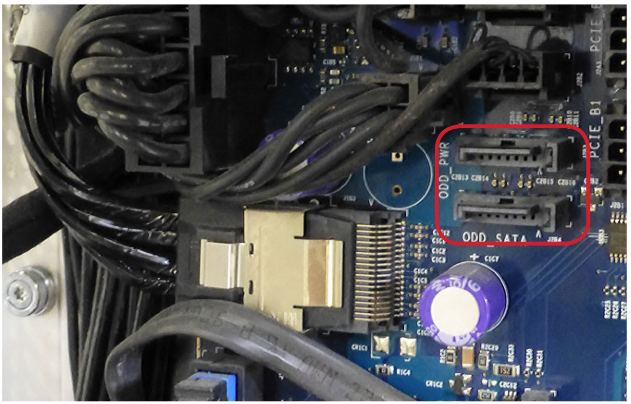
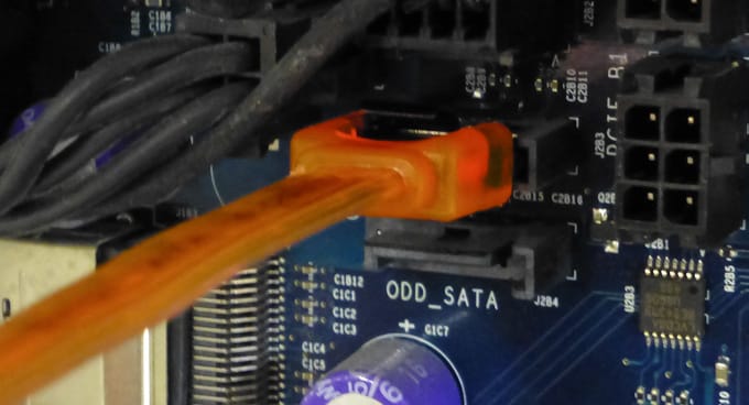
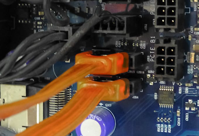
1. Now that you have fully exposed the logic board, look for the two available SATA ports, circled below. Note: your logic board may have a slightly different appearance but the ports will look the same as those shown below.
2. Insert the straight connector on one of the included SATA cables into the upper SATA port on the logic board.
3. Insert the straight connector on the second SATA cable into the lower SATA port on the logic board.
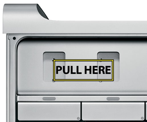
4. Grasp the optical drive carrier and pull it towards you. You may have to wiggle the carrier a bit to dislodge it. Before fully removing the carrier, disconnect any power and ATA cables from the back of the optical drive, then set the carrier aside.
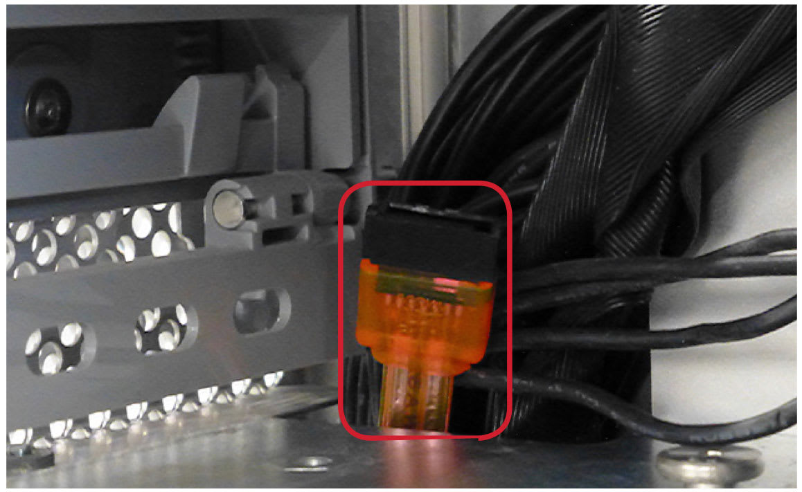
5. Route the two SATA cables up through the corner of the optical bay -- follow the existing wires, as shown below. If possible, route the cables behind the logic board connector for Drive Tray #1. Make sure the cables are not protruding into the fan assembly area before proceeding.
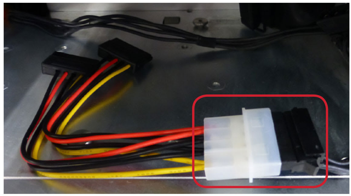
6. You will also need to connect the 4-pin Power to SATA Power Adapter Cable (shown below) before installing and connecting the drives shown in the next section. NOTE: the cable shown below may differ in appearance from the cable in your kit, however the method of connecting the adapter cable is the same.
Assembly & Installation
3.1 Installing 3.5 Inch SATA Drives
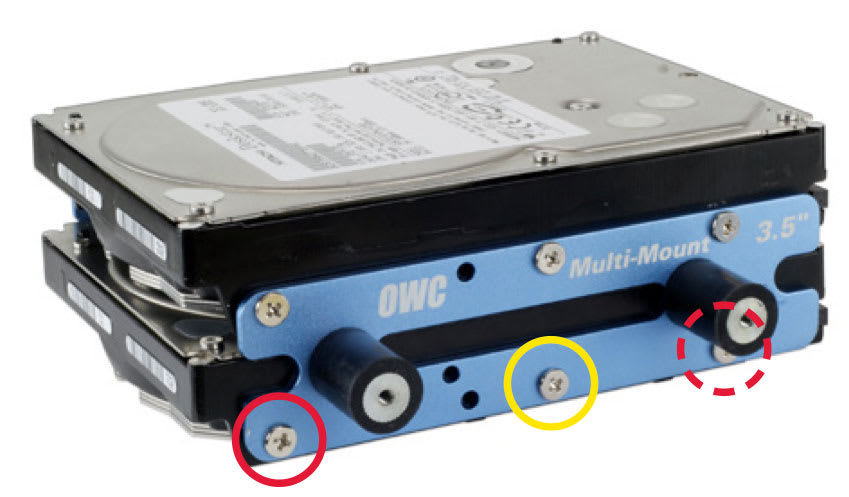
- Position the bottom 3.5 inch drive so the SATA and power ports face to the right, then position the drive bracket labeled ‘Multi-Mount 3.5″’ as shown.
- Attach the drive to the Multi-Mount using the center screw hole and one of the coarse-thread mounting screws; do not fully tighten it.
- Attach a second screw to the left-most or right-most screw hole in order to center the bracket on the drive. Afterward you can insert the remaining screw, then fully tighten all three screws. If you intend to install a second 3.5 inch drive, follow Steps 1-3 again, except that you will use the corresponding screw holes along the top of the bracket.
- Once you have the first bracket installed, rotate the drive and the attached bracket, then affix the opposing bracket using the method described in steps 1-3. Once the second bracket is affixed, the 3.5 inch Multi-Mount assembly is ready to be installed into your system.
Note
You do not have to install two drives into the bracket; a second drive can be added at a later time. The process described above works for both SATA and IDE drives. If you do install two 3.5 inch drives, there will not be room to include an optical drive in the optical bay drive cage.
3.2 Installing a 2.5 Inch SATA Drive
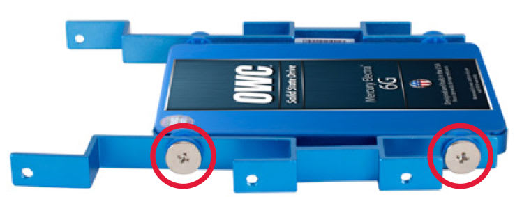
- To install a 2.5 inch SATA drive into the Multi-Mount, place the drive in front of you, with the SATA and power ports facing to the right (as shown). Position the two drive brackets as shown.
- Use the large Phillips screws (pre-attached) to affix the drive to the front bracket. Each screw hole also has a grommet that is pre-attached to the bracket. The grommets are used for vibration reduction; do not remove them.
- Rotate the drive and brackets then affix the rear bracket using the large Phillips screws. Make sure all four screws are tightened. The 2.5 inch Multi-Mount assembly is now ready to be installed into a 3.5 inch drive bay or the 3.5 inch brackets.
3.3 Installing two 2.5 Inch SATA Drives
1. You can install two 2.5 inch SATA drives onto the 3.5 inch drive brackets. Note the orientation of the two types of brackets, shown below-left. The same screw holes are used to affixed 2.5 inch drive assemblies and 3.5 inch drives (see Section 3.1 Installing 3.5 Inch SATA Drives).

3.4 Combining 2.5 and 3.5 Inch Drives
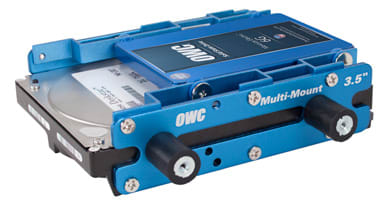
The image at right shows a hybrid configuration that includes a 2.5 inch and a 3.5 inch SATA drive. When installing the 2.5 inch drive assembly into the 3.5 inch brackets, be sure to orient the assembly so that the ports on both drives are facing the same direction, as shown.
3.5 Installing the Multi-Mount into a Mac Pro
The Mac Pro’s optical bay can support a total of two SATA devices.
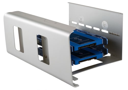
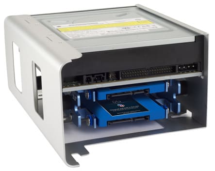
1. Attach the completed Multi-Mount assembly to the optical drive cage using the four screws that Apple supplies (shown below). The screws should be attached to the cage.
2. Once the Multi-Mount is secured, carefully slide the cage back into the optical bay, threading the large cutouts on the bottom of the cage with the large screws on the bottom of the bay.
3. When the cage is about half way in, connect the SATA devices’ cables, then slide the cage the rest of the way until it is fully seated. Do not bend or pinch the cables.
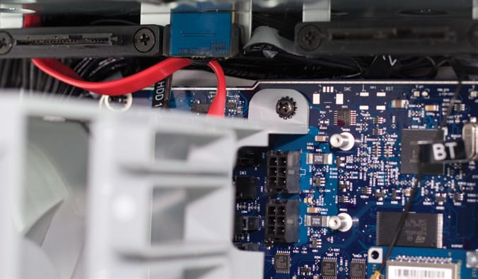
4. Reinsert the fan module into the computer, sliding it on its base track and then reinserting its Phillips screw into the logic board. Note of the location of the SATA cable in this picture (the color of your cable may vary) -- ensure that the cable is not behind the assembly’s mounting bracket when you tighten the screw.
2006-2007 Mac Pro owners:
Work backward through the remaining steps in Section 2.1 to complete reassembly of your Mac Pro.
2008 Mac Pro owners:
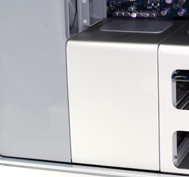
Reinsert the Phillips screw you removed from the base of the fan unit. Replace the processor cover to finish the installation process.
Support Resources
4.1 Troubleshooting
If you’re having trouble with the installation of the OWC Multi-Mount, go back and examine the steps and photographs. Most fit issues can be traced to missing a step or screw. Double check that your brackets are facing the correct direction and that you are not orienting the drive backwards. You want to be sure that the SATA ports are pointing in the right direction for your case installation. Don’t pinch any cables and make certain to not route your wires over sharp edges or corners. If you’re still having trouble, please contact Technical Support (see below).
4.2 About Data Backup
To ensure that your files are protected and to prevent data loss, we strongly suggest that you keep two or more copies of your data on different storage devices and mediums. Any data loss or corruption while using the Multi-Mount is the sole responsibility of the user, and under no circumstances may OWC, its parents, partners, affiliates, officers, employees, or agents be held liable for loss of the use of data including compensation of any kind or recovery of the data.
Changes
The material in this document is for information purposes only and subject to change without notice. While reasonable efforts have been made in the preparation of this document to assure its accuracy, OWC, its parent, affiliates, officers, employees, and agents assume no liability resulting from errors or omissions in this document, or from the use of the information contained herein. OWC reserves the right to make changes or revisions in the product design or the product manual without reservation and without obligation to notify any person of such revisions and changes.
Health And Safety Precautions
- Use proper anti-static precautions while performing the installation of this product.
- Read this manual carefully and follow the correct procedures when setting up the device
General Use Precautions
- For up-to-date product and warranty information, please visit the product web page.
Copyrights and Trademarks
No part of this publication may be reproduced, stored in a retrieval system, or transmitted in any form or by any means, electronic, mechanical, photocopying, recording or otherwise, without the prior written consent of OWC.
© 2017 OWC. All rights reserved.
OWC and Multi-Mount are a trademarks of New Concepts Development Corporation, registered in the U.S. Patent and Trademark Office and/or in Canada. The OWC logo is a trademark of New Concepts Development Corporation. Apple, Mac, and Mac Pro are trademarks of Apple Inc., registered in the United States and other countries. Other marks may be the trademark or registered trademark property of their owners.
Free Support Chat
Our free award-winning support team is ready to answer all of your questions. Technical support is available Monday - Friday: 9AM - 6PM. Customer Support & Sales is available Monday - Friday: 9AM - 6PM. Support is unavailable on U.S. Federal holidays. Talk to a human today.


 1-800-275-4576