 1-800-275-4576
OWC Dual Drive Dock (USB-C) PSU Installation Guide
Support Article
Relevant Part Numbers
- OWCTCDRVDCKPSU
- OWCTCDRVDCKSN
- OWCTCDRVDCK
Instructions
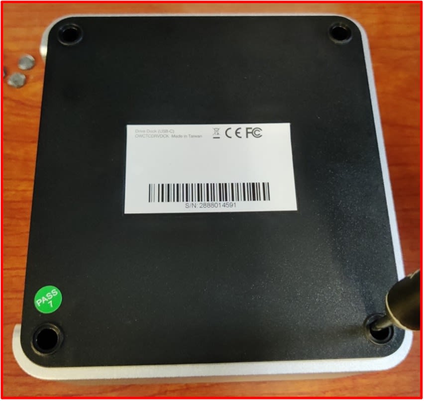
1. Place the OWC Dual Drive Dock upside down on a static free work surface.
- Remove the rubber feet to access the case screws. Safely store the rubber feet for reassembly.
- Remove the case screws. Initially pressing down on the screwdriver while turning counterclockwise will help loosen the case screws. Safely store the case screws for reassembly.
- Please Note: The case screws are deep within the mounting holes; therefore, a long thin PH00 screwdriver will be needed to reach the case screws.
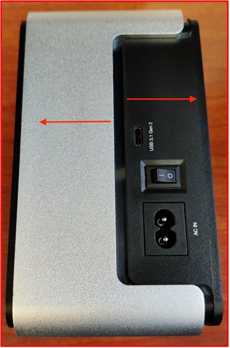
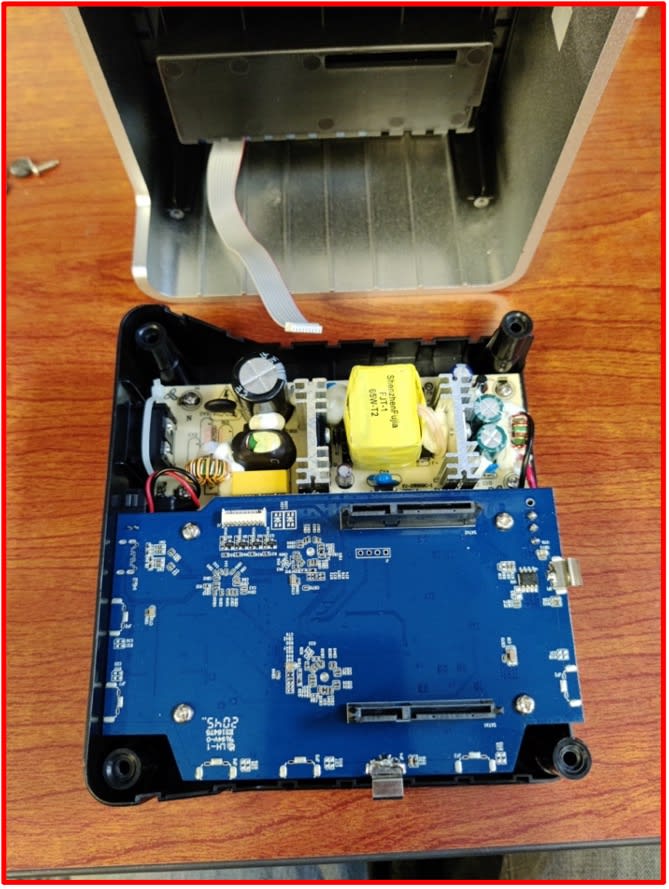
2. Separate the top casing and bottom base by pulling the silver casing in the opposite direction of the black base.
- Please Note: The components will feel tight. Separating the silver casing and black base will feel like taking a tight cover off a bucket.
- Please Note: There is ribbon cable connected from the drive bay to the board inside. The drive bay ribbon cable is not long enough to remain connected with the silver casing while resting on a flat surface. The drive bay ribbon cable will need to be disconnected while holding the silver casing. This is covered in the next step.
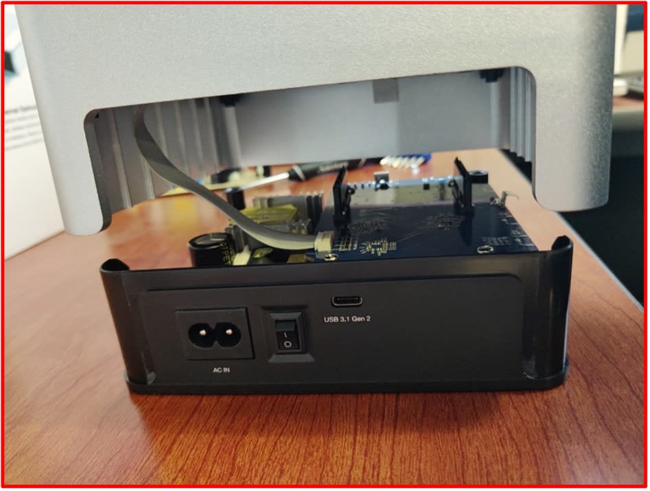
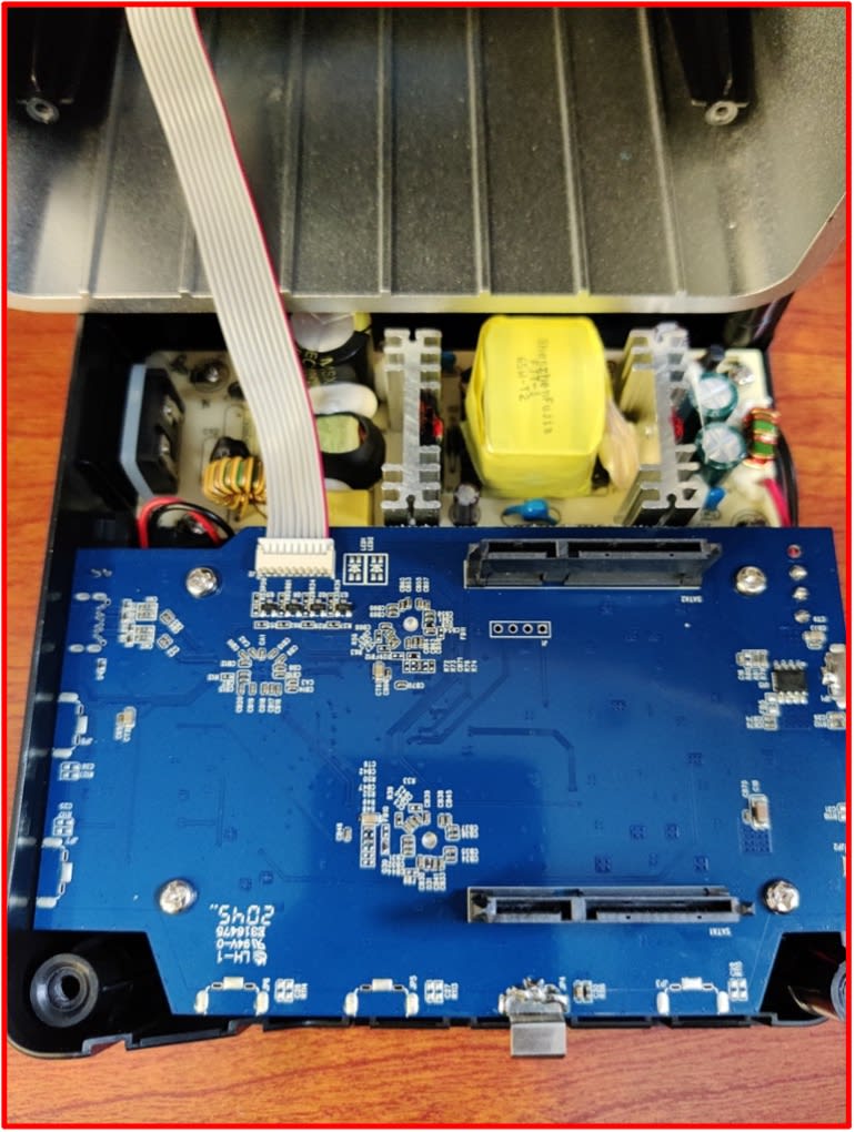
3. Carefully separate the silver casing from the black base ensuring the ribbon cable is not forcefully disconnected.
- Carefully disconnect the drive bay ribbon cable by pulling on the connector while holding the silver casing.
- Please Note: The cable should be disconnected by pulling directly on the connector. Do not disconnect the ribbon cable by pulling on the cable.
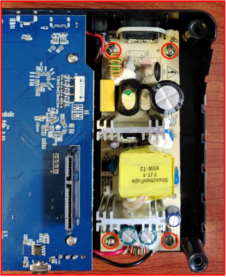
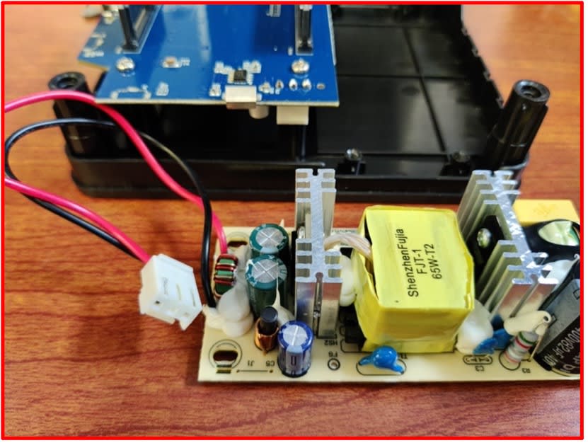
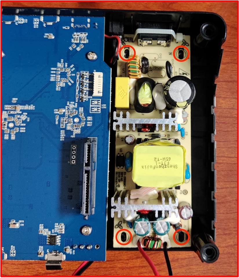
4. Remove the power supply screws (highlighted) using a PH00 screwdriver. Safely store the power supply screws for reassembly.
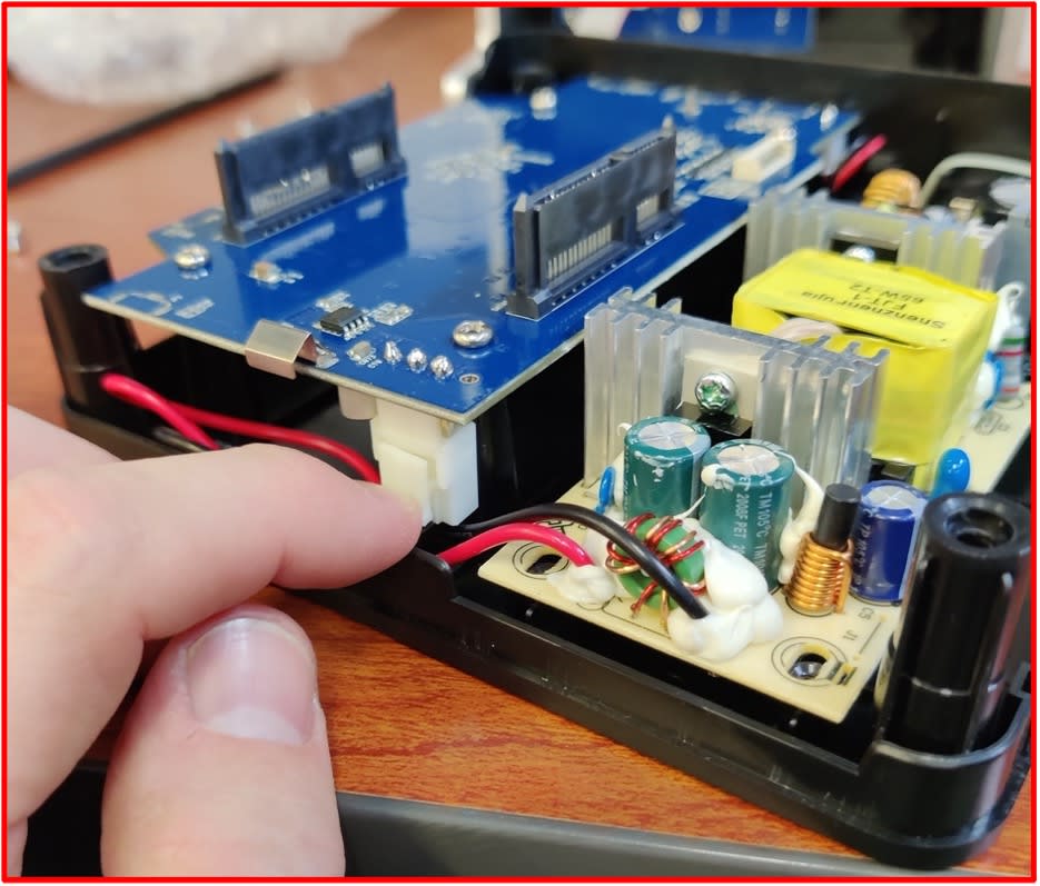
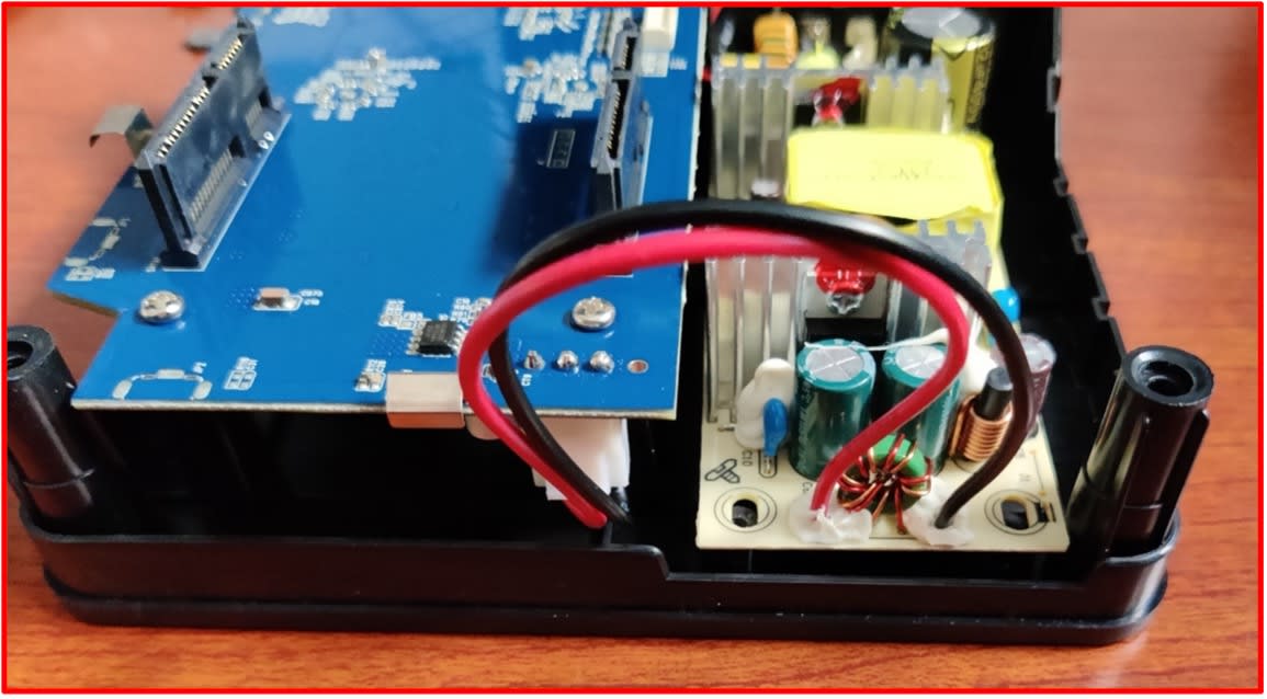
5. Unclip the power supply cable by pushing down on the clip with your finger.
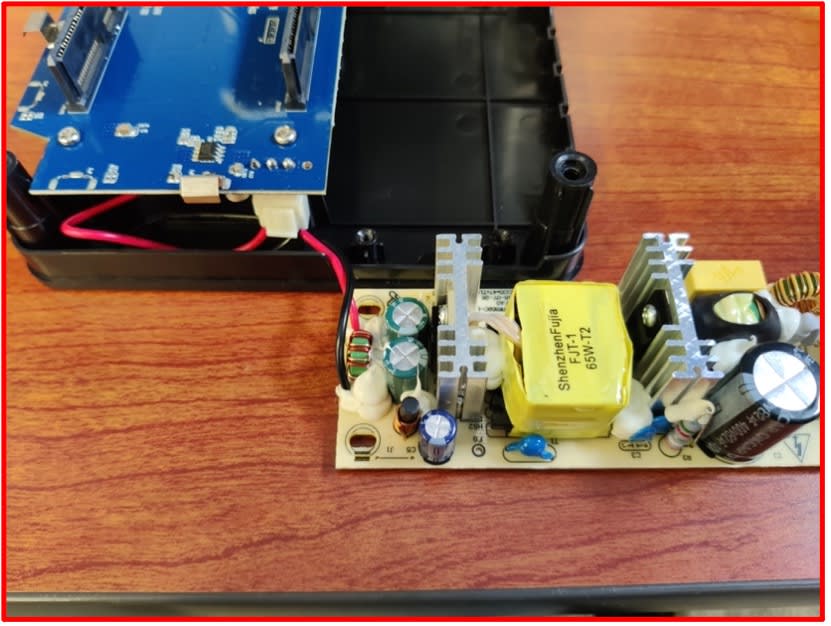
- Slide the power supply away from the housing, and carefully lift the power supply and place it outside the black base.
- Carefully wiggle the unclipped power supply cable out of position until completely free.
- Untuck the wiring and completely remove from the black base.
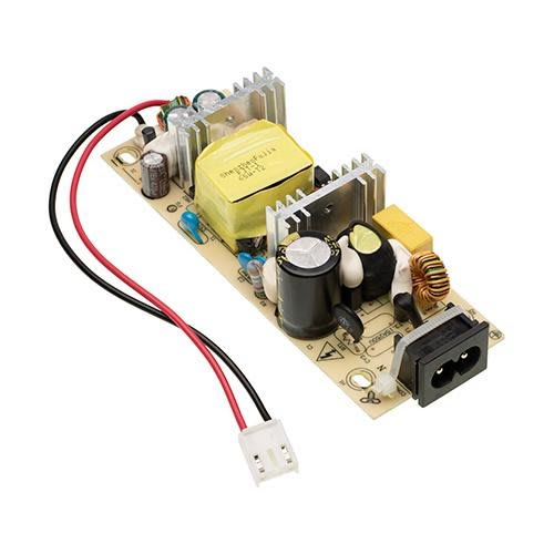
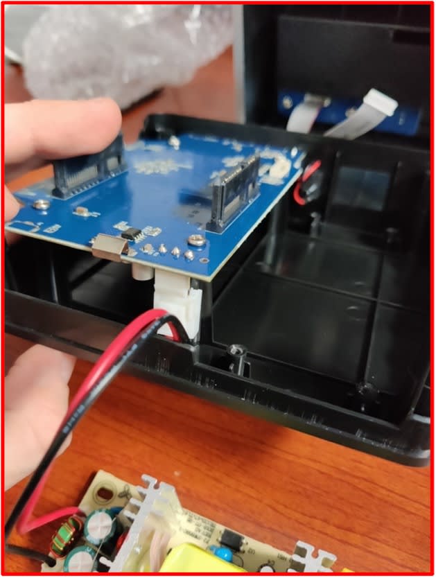
6. The new power supply cable will be connected before installing into the black base.
- Carefully bend the wire slightly to allow easier placement into the black base.
- Place the power supply cable into the black base directly under the power supply connection. Fully connect the power supply cable.
- Please Note: You should hear a light clicking sound indicating the power supply cable is properly connected.
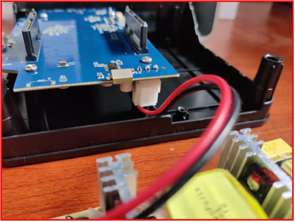
7. Place the new power supply into the black base, and slide the power supply so the connector is slotted into the housing hole.
- Ensure the mounting holes on the power supply board are lined up with the mounting holes on the black base.
- Please Note: The power supply wiring will remain loose until the power supply is mounted to the black base. The wiring will be tucked during Step 9.
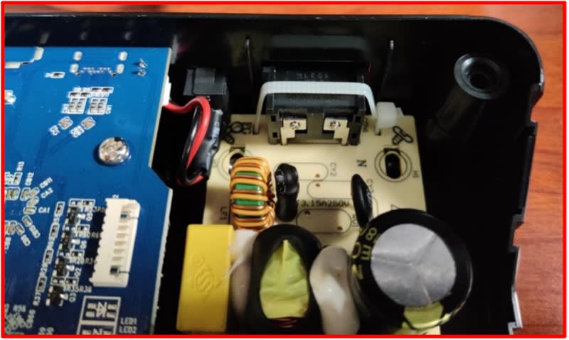
8. Secure the power supply to the black base (highlighted) using the power supply screws that were removed during Step 4.
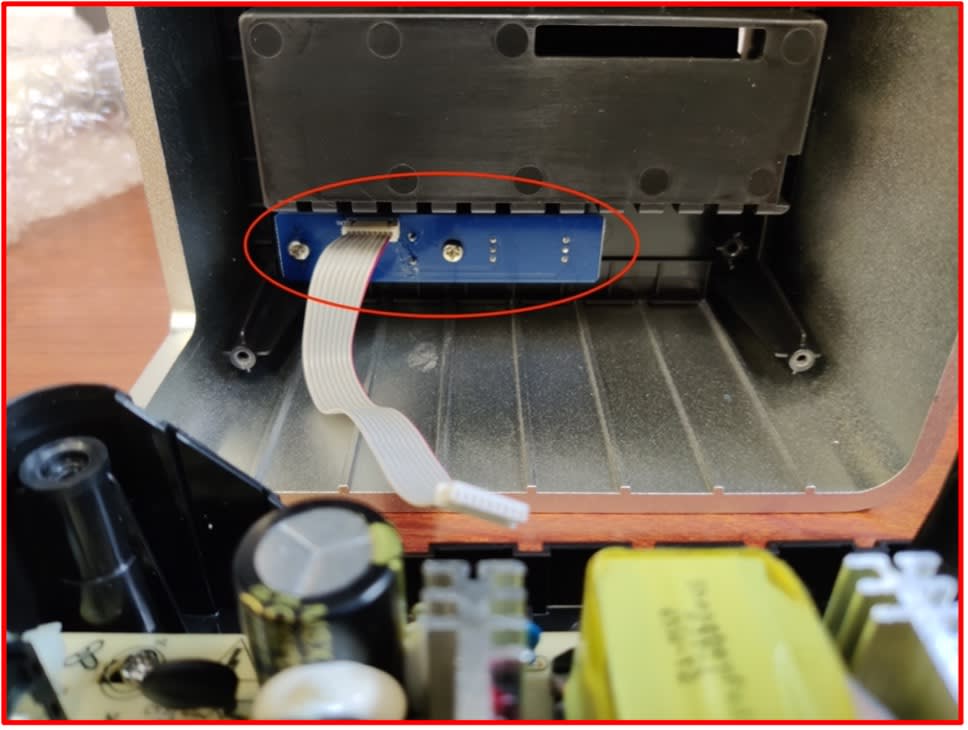
9. Carefully tuck the power supply wiring into the black base under the blue board.
10. Align the drive bay ribbon cable with the drive bay ribbon cable connection and carefully press them together.
- Please Note: Connecting the drive bay ribbon cable will feel a bit tricky as you must hold the silver casing while connecting the cable. The cable is not long enough to remain connected with the silver casing while resting on a flat surface.
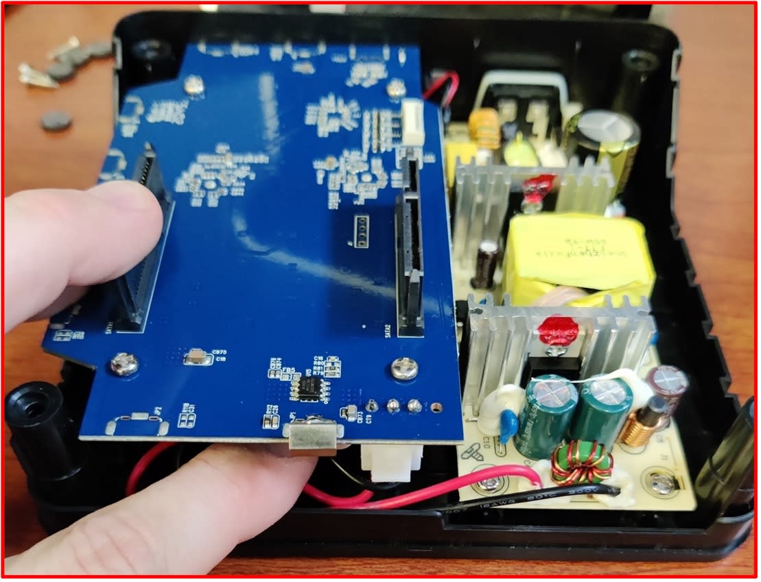
11. Place the silver casing over the black base.
- Ensure the smaller blue board (highlighted) will be over the new power supply when the silver casing is pressed into the black base.
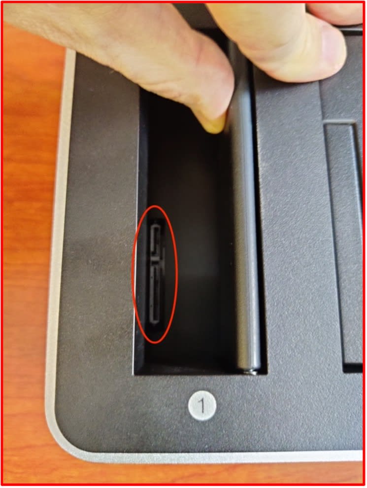
- Check that the SATA connections are peeking through the silver casing (highlighted) before fully pressing the silver casing and black base together.
12. Secure the silver casing and black base by installing the case screws that were removed during Step 1. Pressing down on the screwdriver as resistance increases will allow for more rotations creating a stronger hold between the silver casing and black base.
- Please Note: Do not over tighten the mounting screws to avoid stripping the mounting screw heads. Adhere the rubber feet over the mounting screw holes that were removed during Step 1.
This completes the removal and installation of an OWC Dual Drive Dock power supply. Please contact our Technical Support if you encounter any issues during or after the installation.
Free Support Chat
Our free award-winning support team is ready to answer all of your questions. Technical support is available Monday - Friday: 9AM - 6PM. Customer Support & Sales is available Monday - Friday: 9AM - 6PM. Support is unavailable on U.S. Federal holidays. Talk to a human today.