


 1-800-275-4576

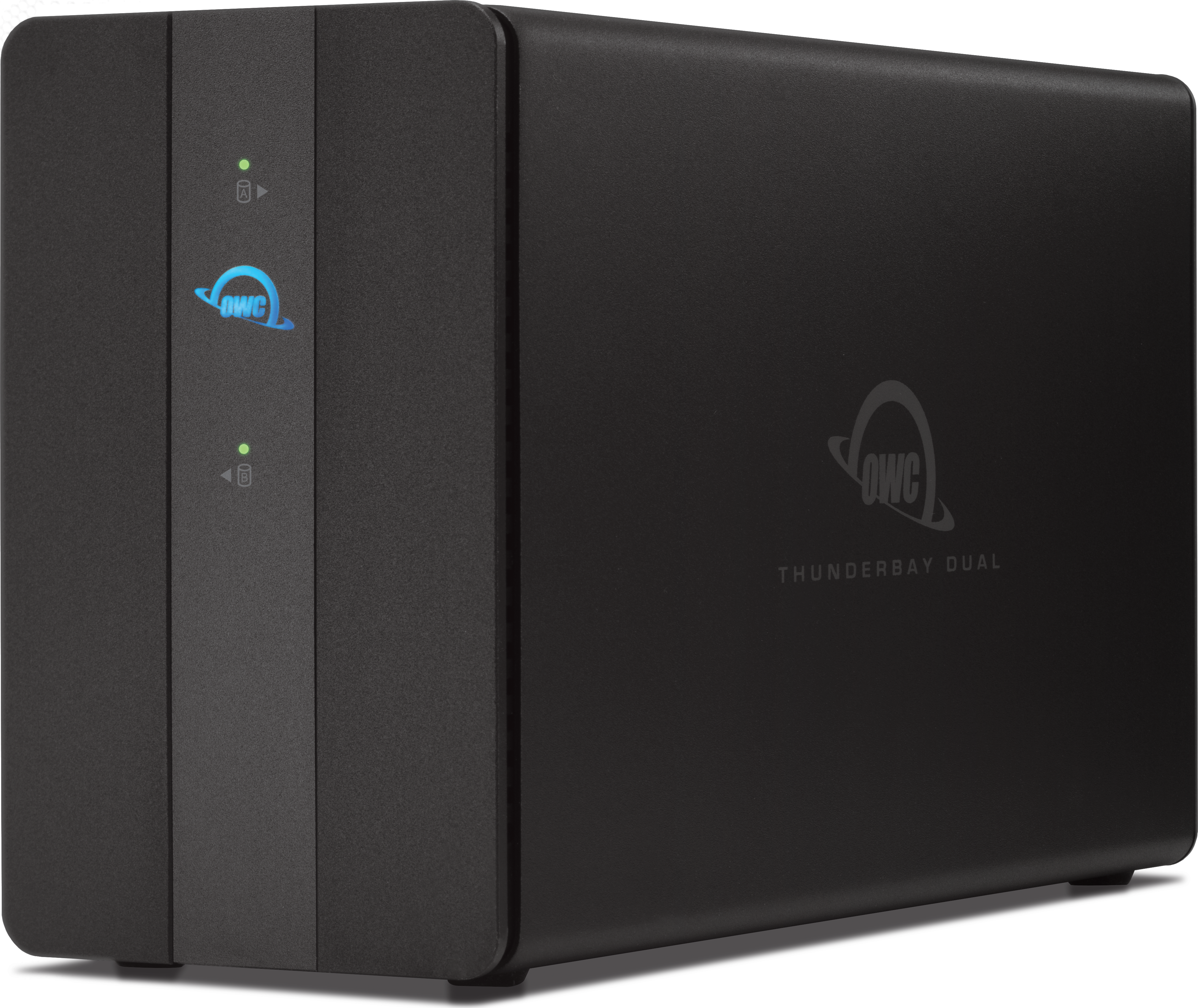
OWC Thunderbolt 5 ThunderBay Dual
Support Manual
Introduction
1.1 System Requirements
Works with any Thunderbolt 5 | Thunderbolt 4 | Thunderbolt 3 (Mac Only) | USB4 | USB-C equipped:
- Mac: macOS 14.x or later
- Thunderbolt 5 requires macOS 15.3.x or later
- Thunderbolt 3 requires macOS 15.x or later
- Intel based Mac systems require macOS 15.x or later
- PC: Windows 10 or later
- Thunderbolt 5 requires Windows 11 or later
- Linux: current Ubuntu version recommended
- Chromebook: current ChromeOS version recommended
- iPad Pro: current iPadOS version recommended
- Android: current Android version recommended
Supported Drives
- 3.5”/ 2.5” SATA HDDs/SSD
- 3.5”/ 2.5” NVMe U.2 SSDs/adapters
- OWC U2 Shuttle sold separately.
- Hardware RAID configurations are not supported. NVMe U.2 SSDs and adapters can be formatted as an individual drive or using a Software RAID such as OWC SoftRAID.
Required Driver
- Windows 10 and Windows 11 users utilizing the OWC Thunderbolt 5 ThunderBay Dual (2.5GbE) ethernet require a network driver.
1.2 Package Contents
- (1) OWC Thunderbolt 5 ThunderBay Dual
- (1) Thunderbolt cable
- (1) External power supply
- (1) Power cable
- (1) 3 Years of SoftRAID Premium Access (with select solutions)
- License located on bottom of device
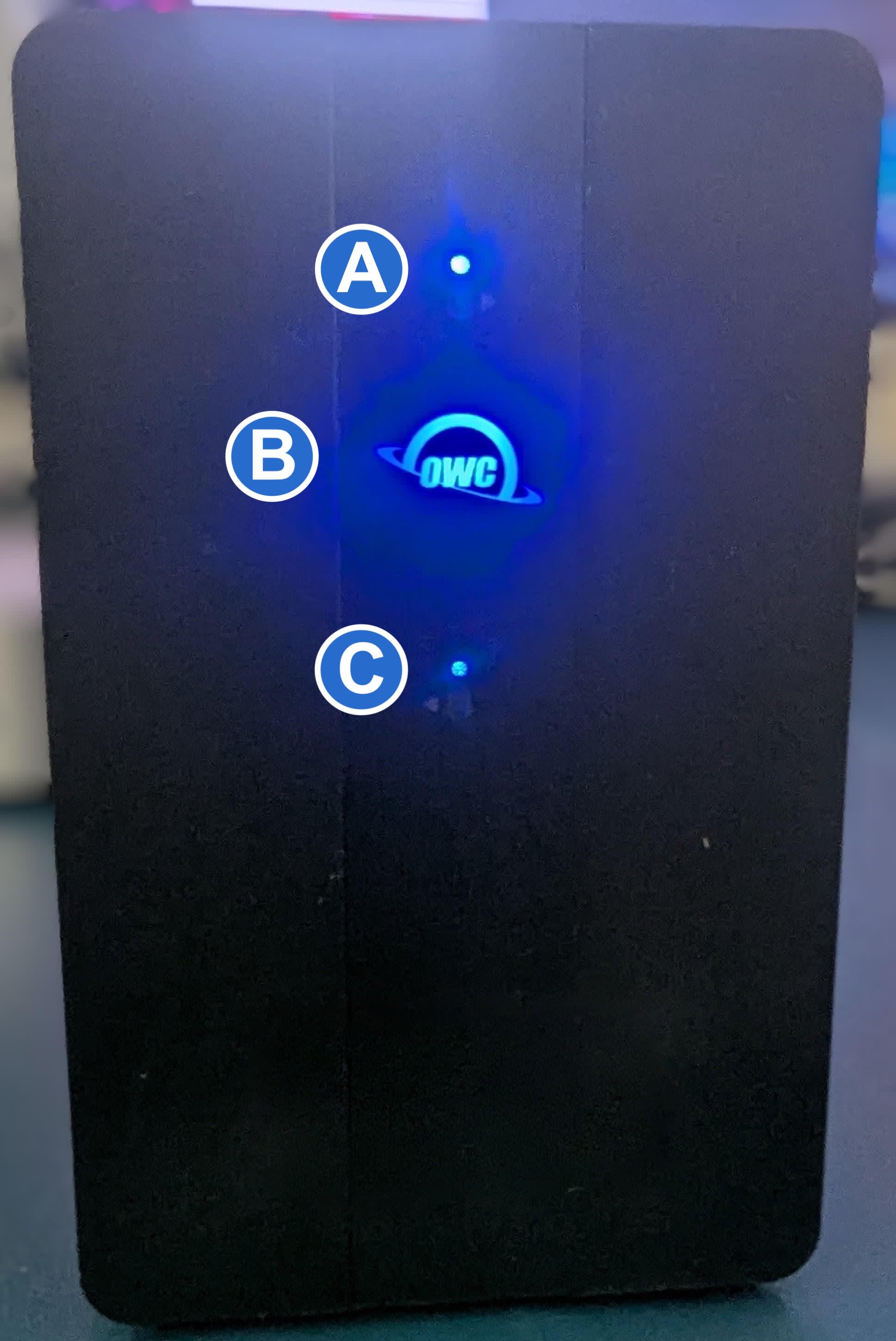
1.3 Front View
A. Drive Bay A Status LED – Solid red for SATA disk errors or missing disks. Blinks blue during drive activity.
- NOTE: Red LED indication for missing or failed drives is disabled for SoftRAID and drives used in Independent Mode.
B. Power LED – Solid white when connected to power. Solid blue when connected to both power and an active system.
C. Drive Bay B Status LED – Solid red for SATA disk errors or missing disks. Blinks blue during drive activity.
- NOTE: Red LED indication for missing or failed drives is disabled for SoftRAID and drives used in Independent Mode.
1.4 Rear View
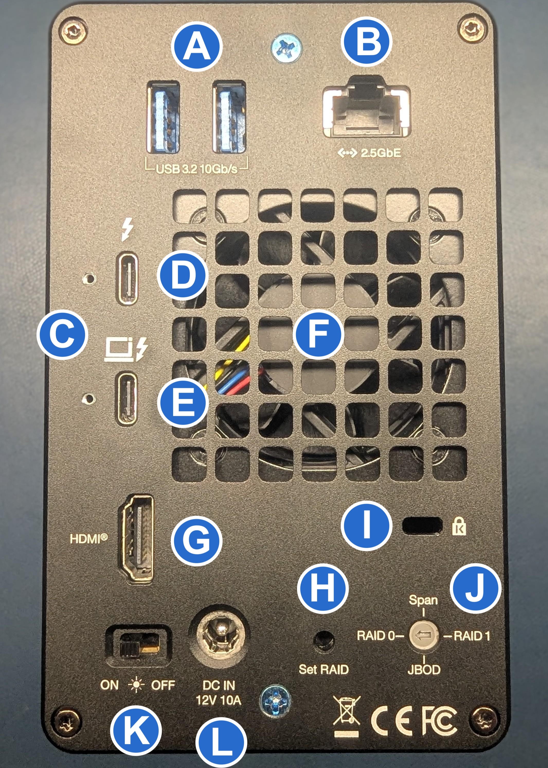
A. (2) USB 3.2 Gen 2 Type-A hub ports – Supports USB devices with a Type-A connection
B. (1) Ethernet port – Provides the host computer with 2.5GbE wired network connection.
- Left LED will show Green for 10M/100M/1G connections.
- Left LED will show solid orange for 2.5G connection.
- Right LED will show solid green for an established link and blink green during network activity.
- Windows 10 and Windows 11 users require a network driver.
- NOTE: The OWC Thunderbolt 5 ThunderBay must be connected to a host system via Thunderbolt (USB-C) and cannot be connected over the Ethernet port.
C. (2) OWC ClingOn ready cable stabilizer mounts – OWC ClingOn can further secure Thunderbolt (USB-C) device cables (Sold separately).
D. (1) Thunderbolt 5 port – xGb/s, yW Dynamic Power Delivery. zW delivery to primary connected system or device. xW delivery to secondary connected system or device.
E. (1) Thunderbolt 5 host port - Connect the included Thunderbolt cable to this port and into a compatible system.
F. (1) Variable Temperature Control Fan - XYZ variables
G. (1) HDMI 2.1 port – Supports a HDMI 2.1 display.
H. (1) Set RAID button - Press this button to set the desired RAID mode selected with the RAID Configuration Dial.
I. (1) Kensington Security slot – Attach a Kensington Security lock.
J. (1) RAID Configuration Dial - Move the dial so the arrow is pointing at the desired RAID configuration.
- See Section 2.4 “Hardware RAID Configuration” for more details regarding RAID management.
K. (1) LED Indicator Switch - Use to toggle the device status LEDs between ON and OFF.
L. (1) DC IN power port - Connect the power adapter to power the device.
Getting Started
2.1 Device Setup
This section describes the process of setting up the OWC Thunderbolt 5 ThunderBay Dual if purchased with pre-installed drives. The OWC Thunderbolt 5 ThunderBay Dual is available with several assembly and configuration variations.
- If the OWC Thunderbolt 5 ThunderBay Dual is assembled with (2) SATA drives.
- Both drives are configured as a Hardware RAID 0.
- If the OWC Thunderbolt 5 ThunderBay Dual is assembled with (1) SATA drive and (1) NVMe drive.
- Both drives are configured as an Hardware Independent RAID.
- If the OWC Thunderbolt 5 ThunderBay Dual is assembled with (2) U2 ShuttleOnes for a total of (2) M.2 NVMe drives.
- Both drives are configured as an OWC SoftRAID RAID 0.
- If the OWC Thunderbolt 5 ThunderBay Dual is assembled with (2) U2 Shuttles for a total of (6) M.2 NVMe drives.
- Both drives are configured as an OWC SoftRAID RAID 0.
1. Plug the power cable into the OWC Thunderbolt 5 ThunderBay Dual DC IN power port located on the back and into a power outlet. The Power LED will illuminate a solid white.
2. Connect the included Thunderbolt cable into the Thunderbolt 5 Host Port located on the back of the OWC Thunderbolt 5 ThunderBay Dual and into a system. The Power LED will illuminate a solid blue.
- NOTE: The OWC Thunderbolt 5 ThunderBay Dual has (1) xGb/s Thunderbolt 5 port with yW Dynamic Power Delivery. zW of power is delivered to the first connected system or device. xW of power is delivered to the second connected system or device.
3. Users operating a Hardware RAID configured OWC Thunderbolt 5 ThunderBay Dual can now begin to use the device. Users operating an OWC SoftRAID Software RAID configured OWC Thunderbolt 5 ThunderBay Dual should continue to either "Mac OWC SoftRAID Setup" | "Windows OWC SoftRAID Setup".
Mac OWC SoftRAID Setup
The OWC Thunderbolt 5 ThunderBay Dual offers multiple drive and RAID configuration options. This device supports 3.5”/ 2.5” SATA and NVMe U.2 drives/adapters.
NOTE: Hardware RAID configurations are not supported with NVMe U.2 SSDs. NVMe U.2 SSDs can be formatted as an individual drive. Installing only (1) NVMe M.2 SSDs via adapter per drive bay is recommended.
- (2) SATA HDDs configured as a Hardware RAID 0, 1, Independent, or Span.
- (1) M.2 NVMe SSD assembled in (1) U.2 adapter (ShuttleOne) formatted as an individual drive, and (1) SATA HDDs configured as a Hardware RAID Independent.
- (2) M.2 NVMe SSDs assembled in (2) U.2 adapters (ShuttleOne) formatted as individual drives.
Windows OWC SoftRAID Setup
- OWC Thunderbolt 5 ThunderBay Dual devices that were bundled with "3 Years of SoftRAID Premium Access" should download and install the latest version of SoftRAID to experience the best performance.
NOTE: OWC Thunderbolt 5 ThunderBay Dual devices configured as a Hardware RAID do not include OWC SoftRAID. - If you are using the OWC Thunderbolt 5 ThunderBay Dual with the Windows operating system, the pre-installed drives need to be reconfigured before they can be used. The following options will allow the Mac formatted OWC Thunderbolt 5 ThunderBay Dual to work as a Windows formatted device.
- Download OWC SoftRAID for Windows
- Please review and follow the steps outlined in OWC SoftRAID Installation for Windows.
- Please consult the support article "Mac to Windows – SoftRAID Volume Conversation" for instructions to convert the Mac formatted OWC SoftRAID RAID to a Windows formatted device through OWC SoftRAID.
- The Mac formatted OWC SoftRAID RAID OWC Thunderbolt 5 ThunderBay Dual can be used in Windows through the purchase and installation of OWC MacDrive. OWC MacDrive allows access to software RAID Mac-formatted drives in Windows without performing a conversion process. Please visit OWC MacDrive Product Details or OWC MacDrive Support for more information.
2.2 Assembly Options
The OWC Thunderbolt 5 ThunderBay Dual offers multiple drive and RAID configuration options. This device supports 3.5”/ 2.5” SATA HDDs/SSD
NOTE: Hardware RAID configurations are not supported with NVMe U.2 SSDs. NVMe U.2 SSDs can be formatted as an individual drive. Installing only (1) NVMe M.2 SSDs via adapter per drive bay is recommended.
- (2) SATA HDDs configured as a Hardware RAID 0, 1, Independent, or Span.
- (1) M.2 NVMe SSD assembled in (1) U.2 adapter (ShuttleOne) formatted as an individual drive, and (1) SATA HDDs configured as a Hardware RAID Independent.
- (2) M.2 NVMe SSDs assembled in (2) U.2 adapters (ShuttleOne) formatted as individual drives.
2.3 Assembly Steps
This section describes the process of installing drives into the OWC Thunderbolt 5 ThunderBay Dual if purchased as a bare enclosure. For maximum performance install identical drives.
Opening the Enclosure
1. Begin by placing the device on a static free work surface and only remove the two highlighted blue phillip screws from the back of the enclosure. Safely store the screws for reassembly.
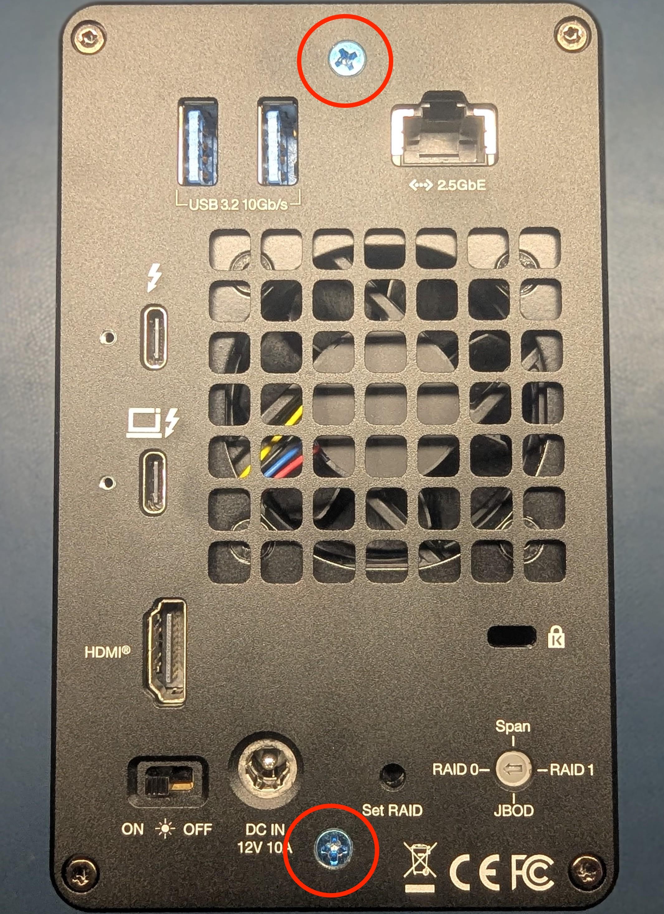
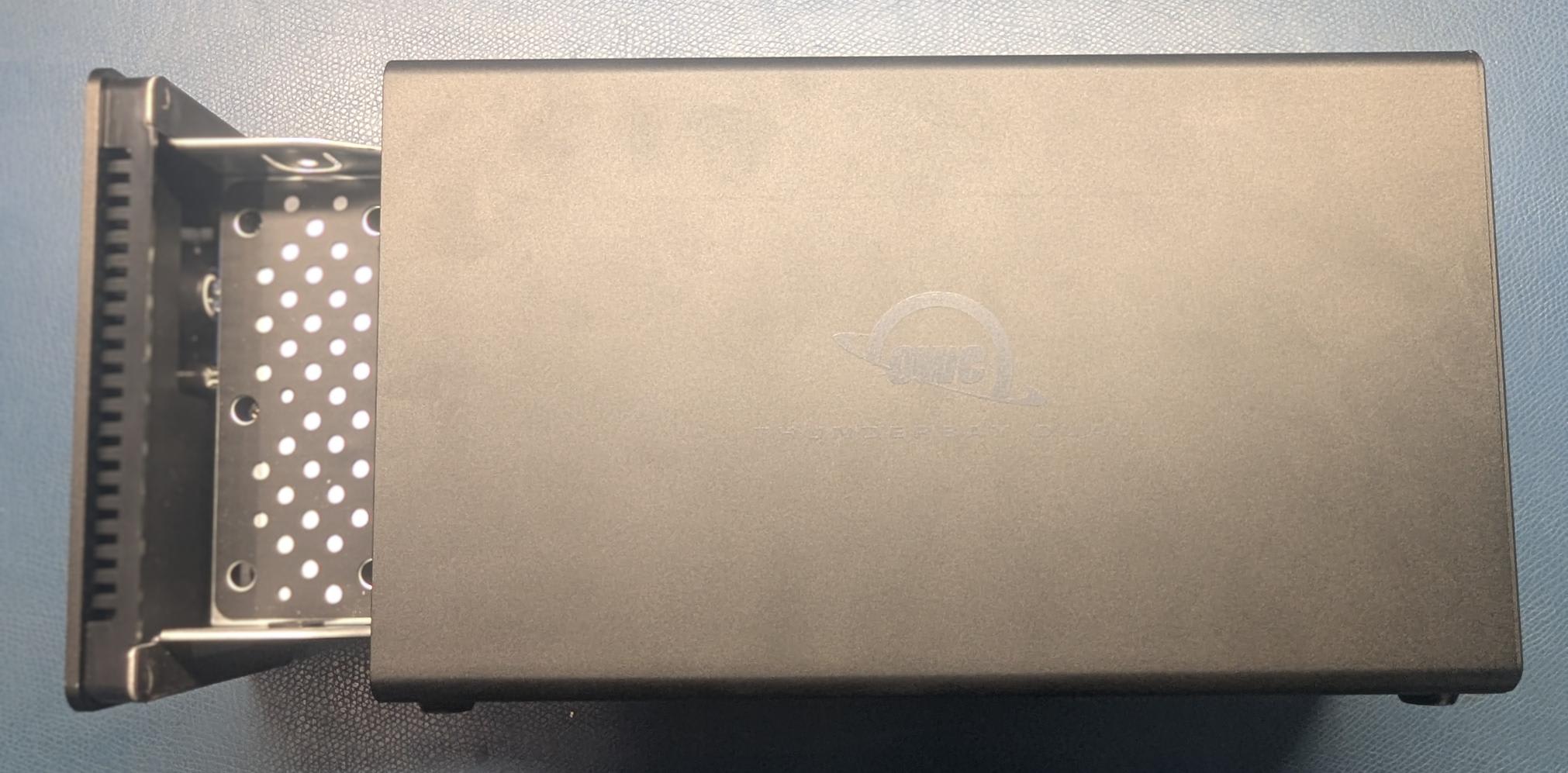
2. Carefully lay the device down so the OWC silkscreen is facing upwards. Pull on the front edge of the inner chassis outwards to remove from the outer chassis.
3.5" HDD/SSD Installation
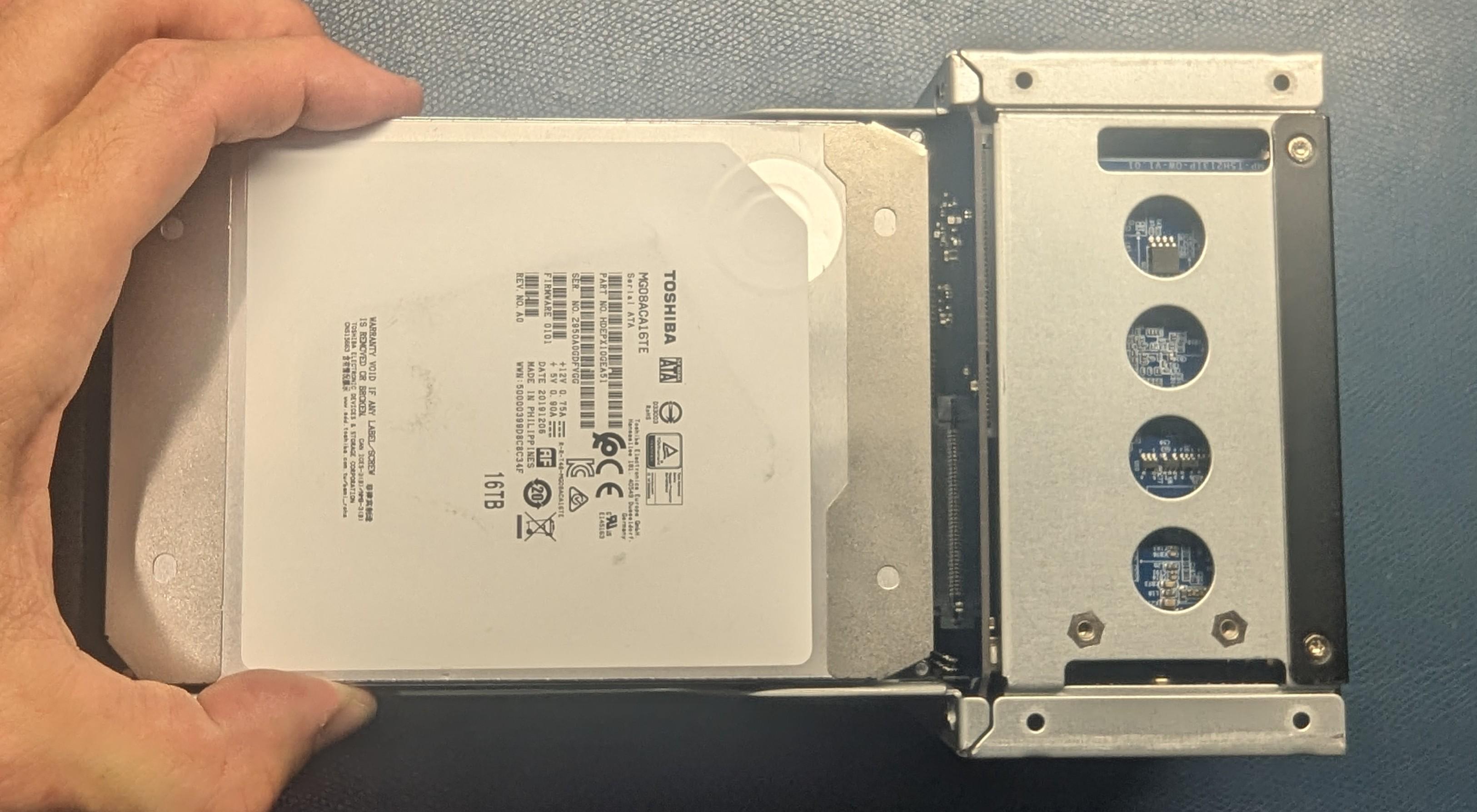
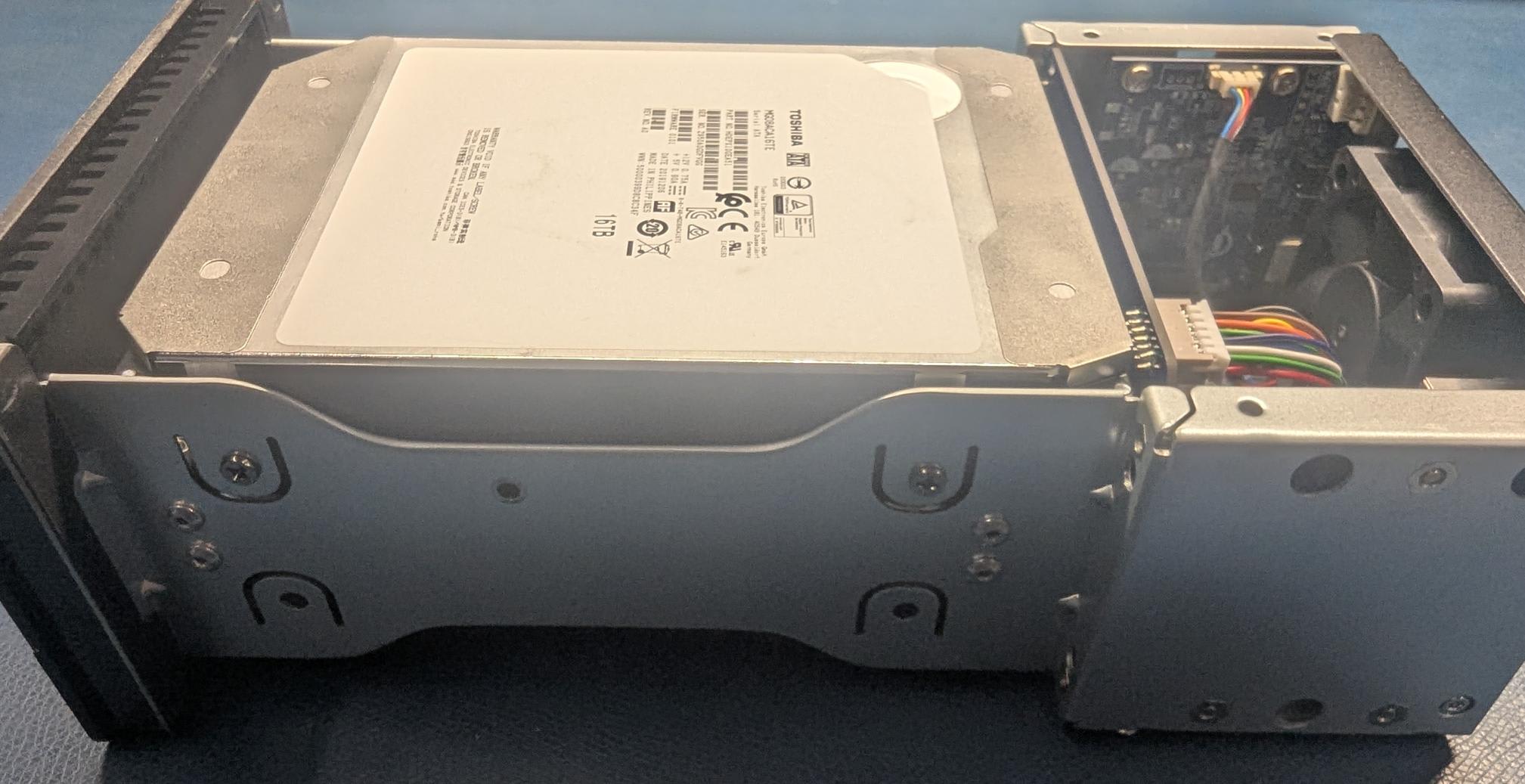
1. Set the inner chassis flat on the work surface and place a 3.5” SATA HDD/SDD into the drive housing. Carefully seat the drive. The drive label should be visible and minimal force is required.
- NOTE: If there is any data on the drives being installed:
- Any data on the drives being installed will be lost when changing the RAID mode.
- If the drives were removed from another OWC Thunderbolt 5 ThunderBay Dual, the data will remain intact if the RAID mode of the OWC Thunderbolt 5 ThunderBay Dual matches the RAID configuration of the drives before installation. Additionally, the OWC Thunderbolt 5 ThunderBay Dual models need to match. Older OWC Thunderbolt 5 ThunderBay Dual models are not compatible.
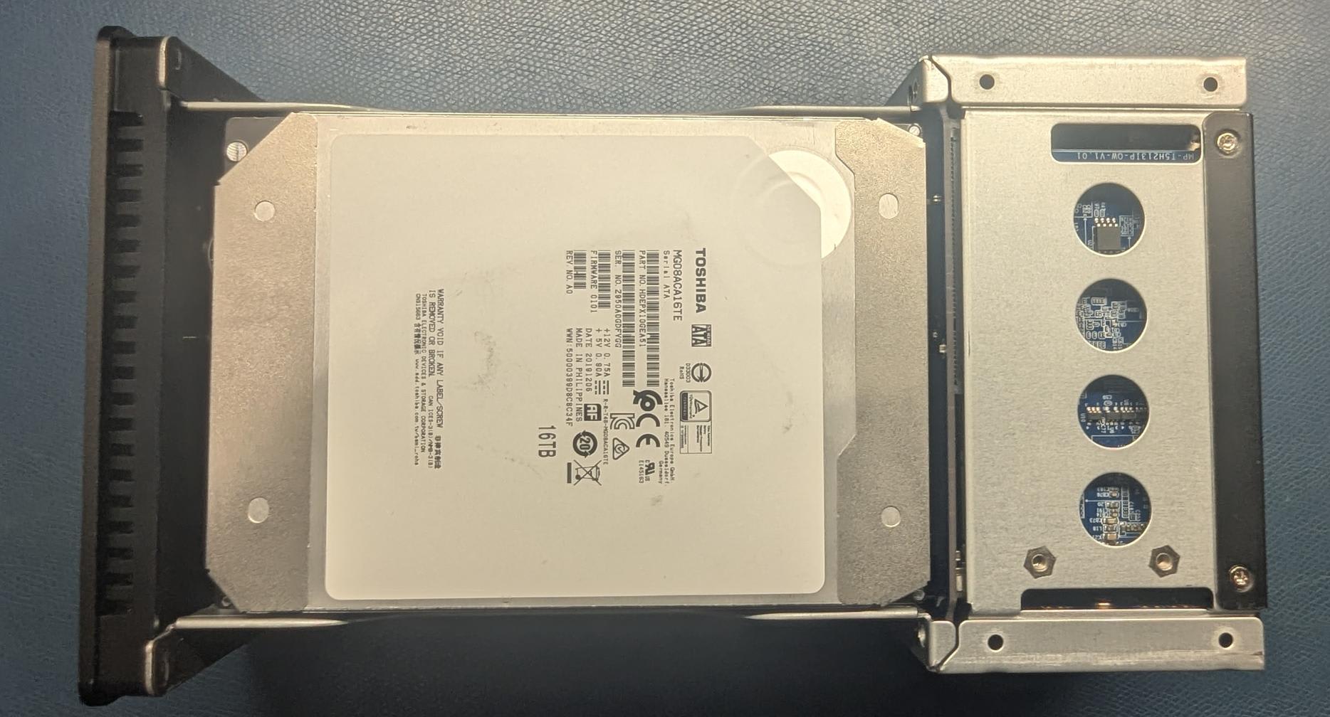
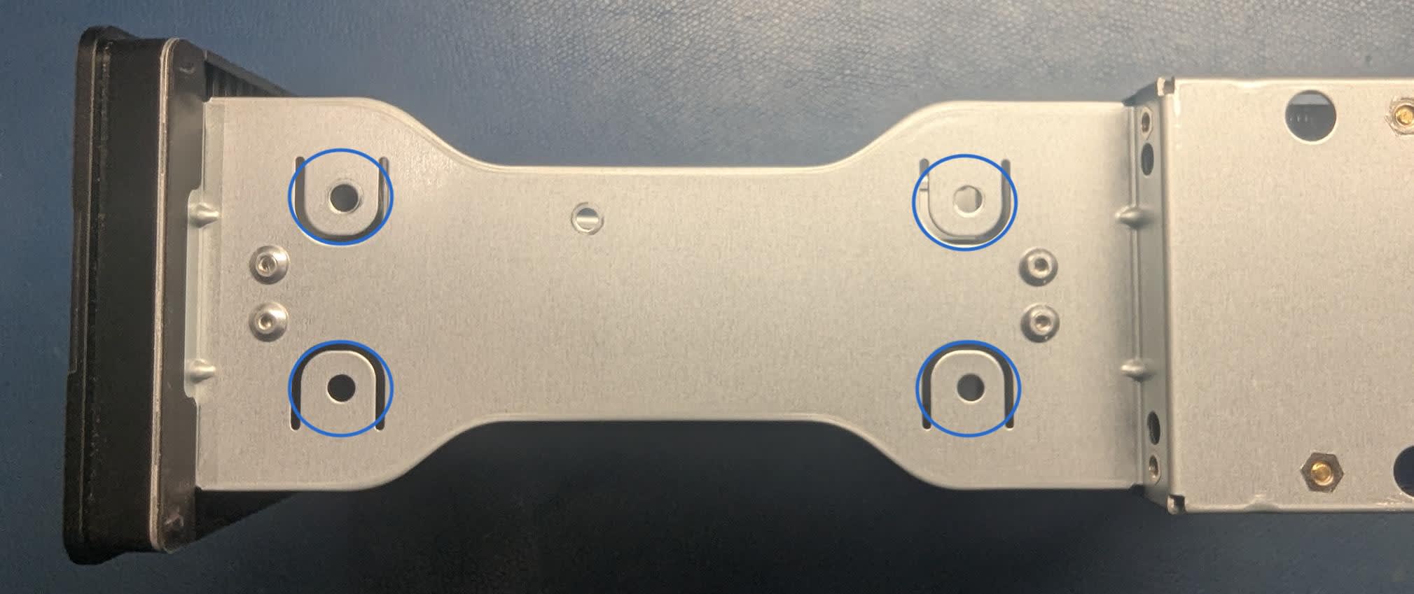
2. Affix the drive to the inner chassis. Holes for 3.5” drive screws are circled in blue.
- NOTE: Apply slight pressure from the backside of the drive while turning the drive screw to help secure the drive properly.
- NOTE: (8) drive screws are required for 3.5” drives, (4) drive screws for each side.
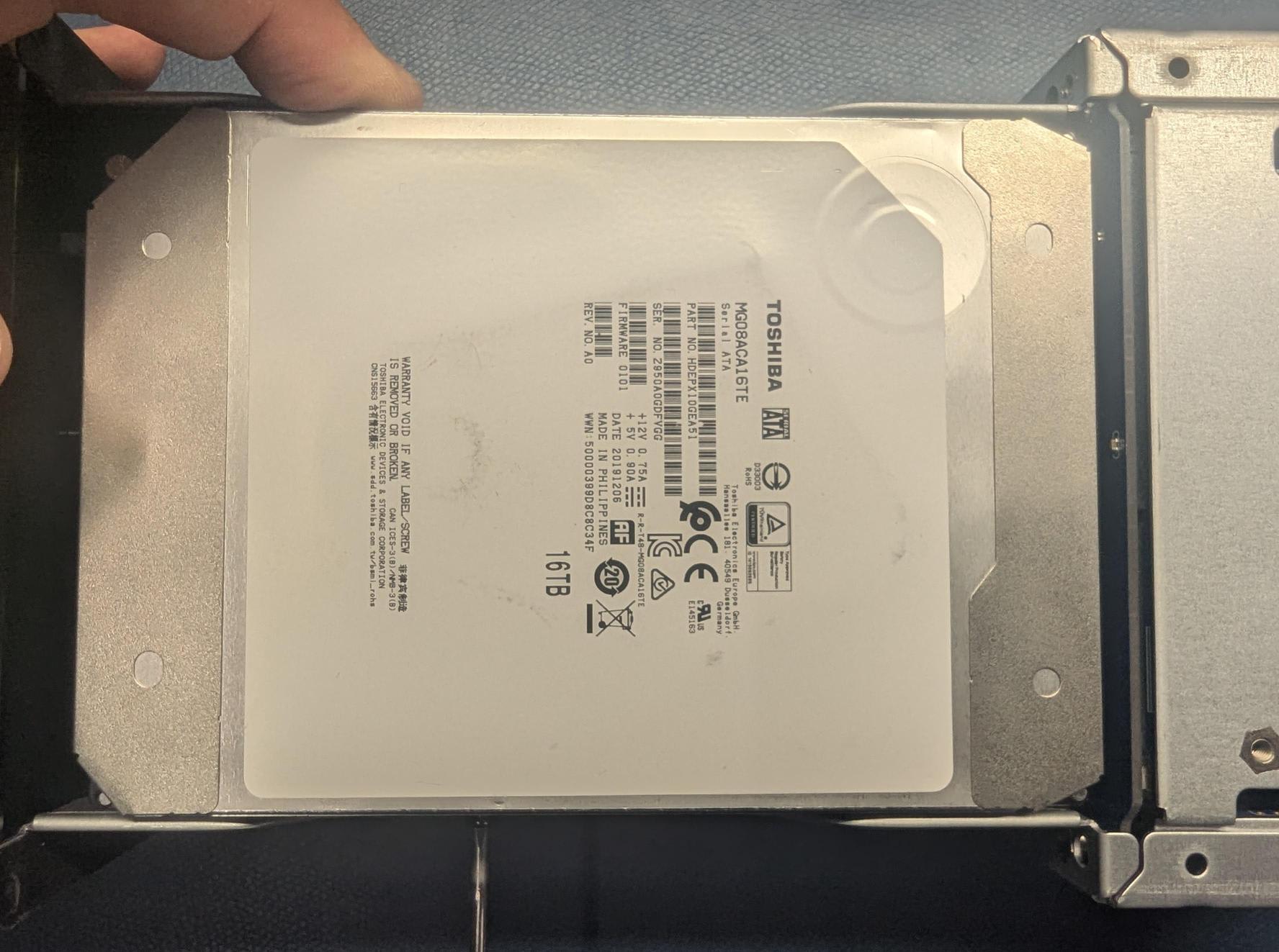
3. Carefully turn the device to the other open drive bay. Carefully seat the drive. The drive label should be visible and minimal force is required.
2.5" HDD/SSD Installation
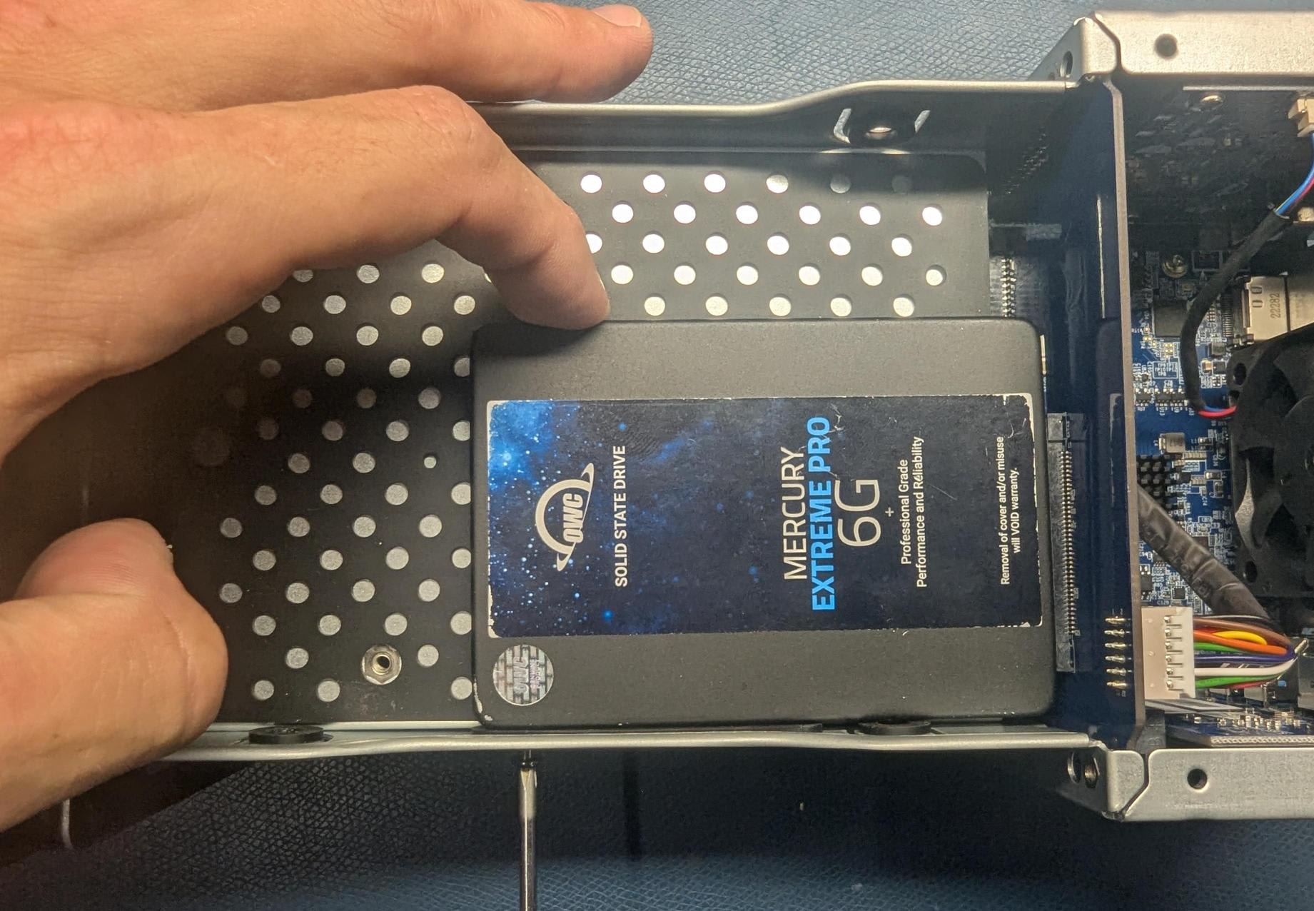
1. Set the inner chassis flat on the work surface and place a 2.5” SATA HDD/SDD into the drive housing. Carefully seat the drive. The drive label should be visible and minimal force is required.
- NOTE: If there is any data on the drives being installed:
- Any data on the drives being installed will be lost when changing the RAID mode.
- If the drives were removed from another OWC Thunderbolt 5 ThunderBay Dual, the data will remain intact if the RAID mode of the OWC Thunderbolt 5 ThunderBay Dual matches the RAID configuration of the drives before installation. Additionally, the OWC Thunderbolt 5 ThunderBay Dual models need to match. Older OWC Thunderbolt 5 ThunderBay Dual models are not compatible.
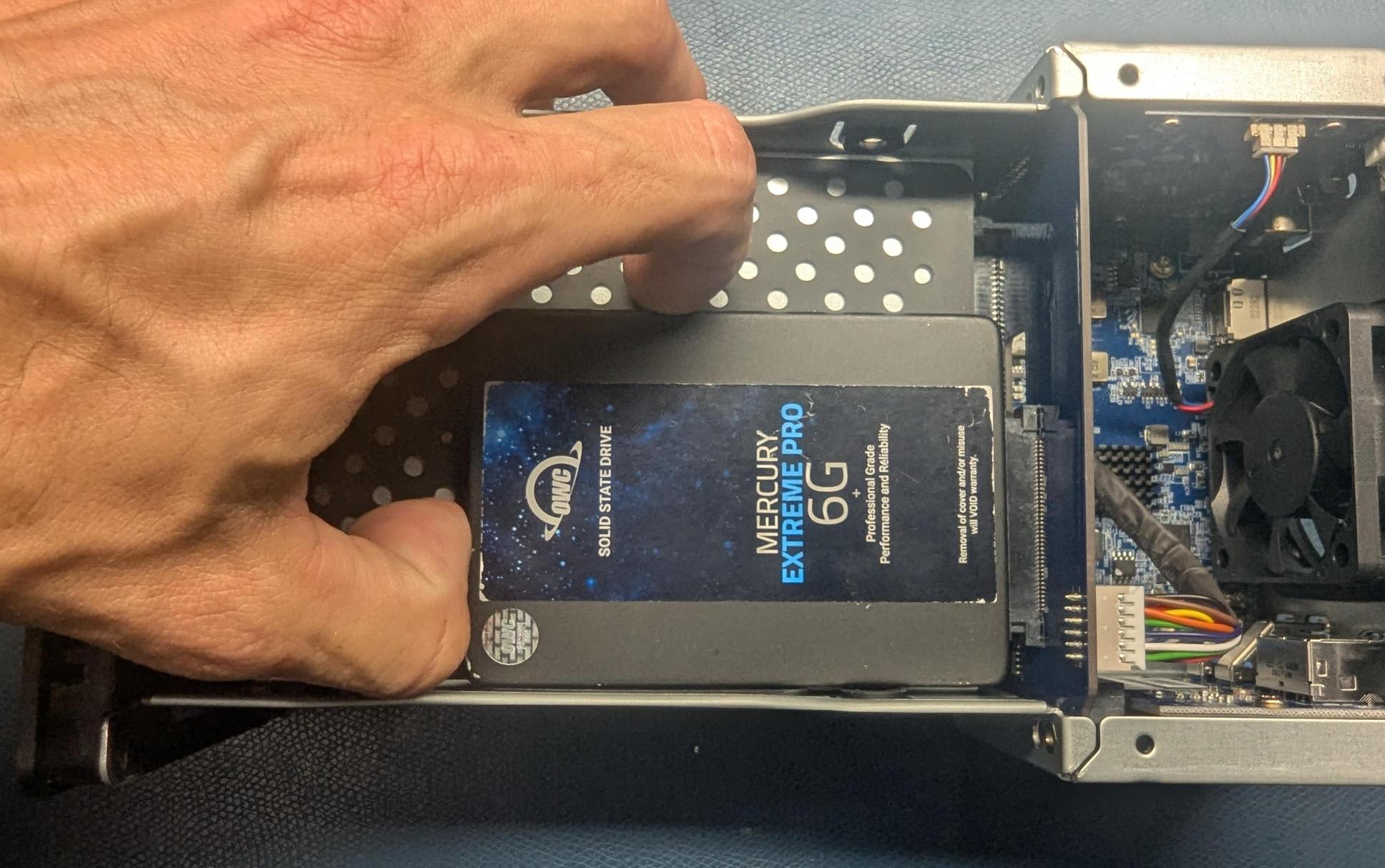
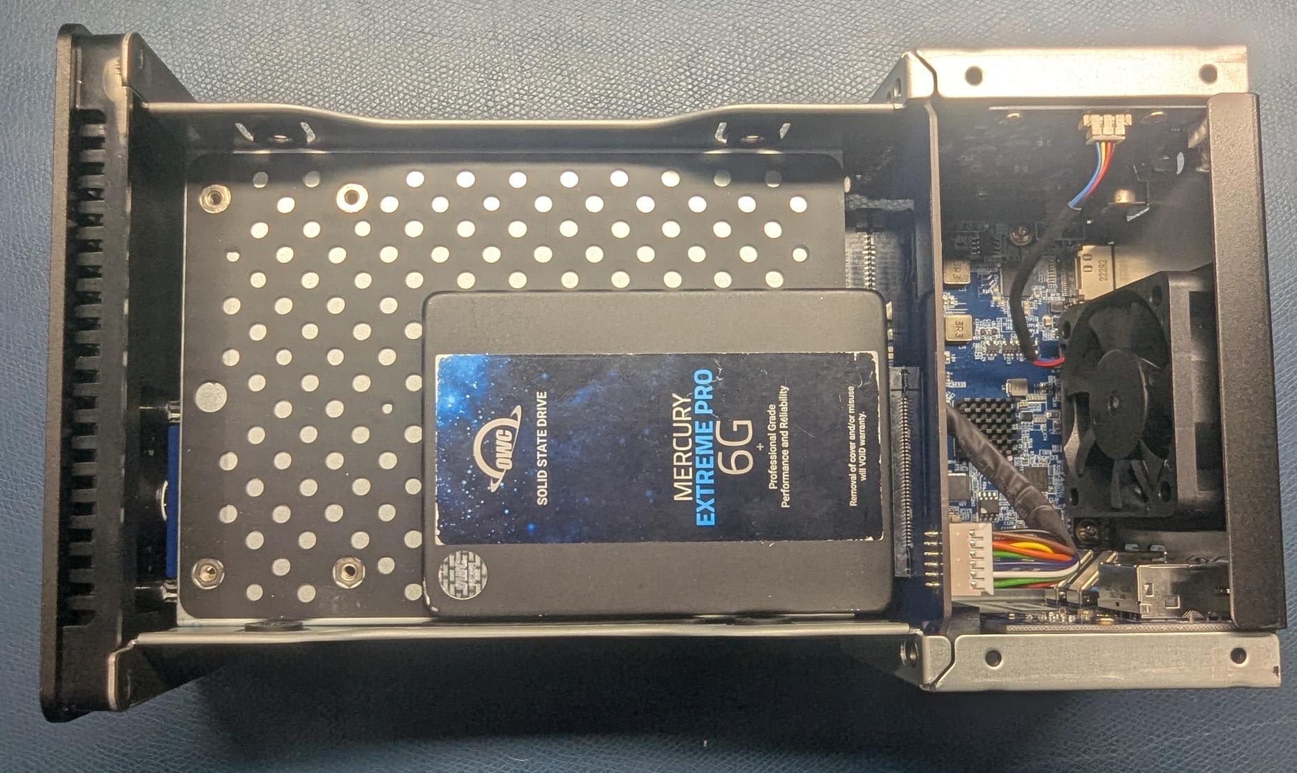
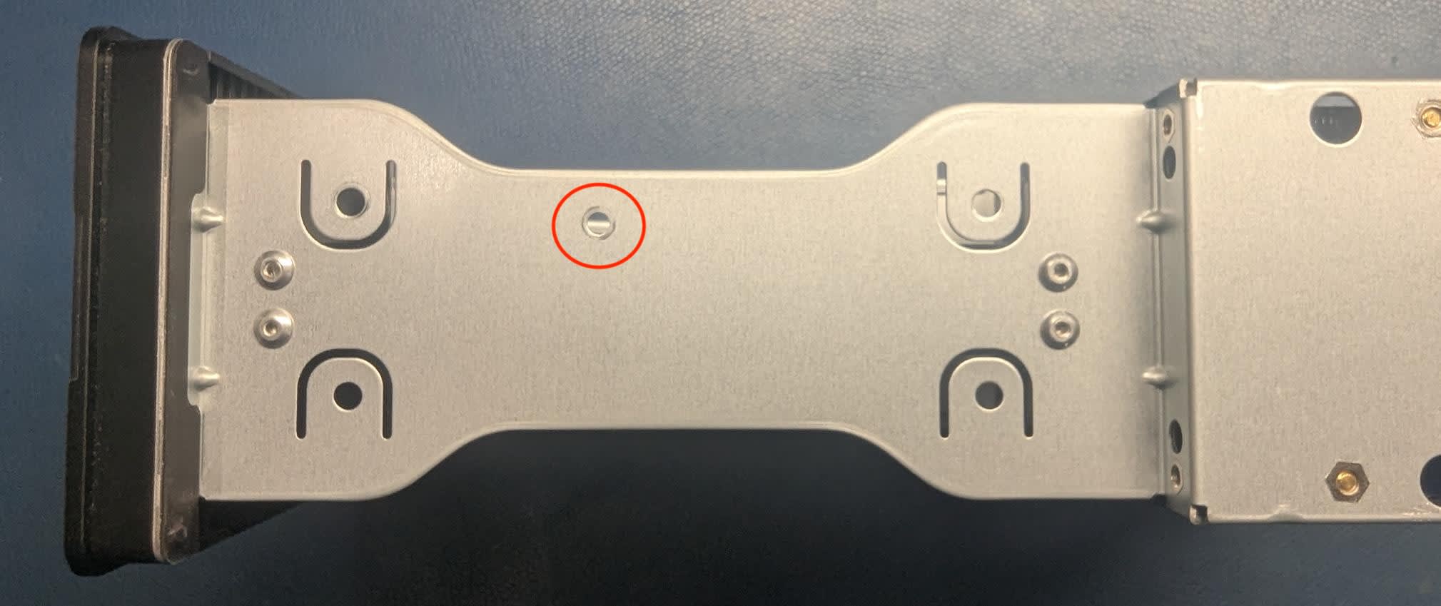
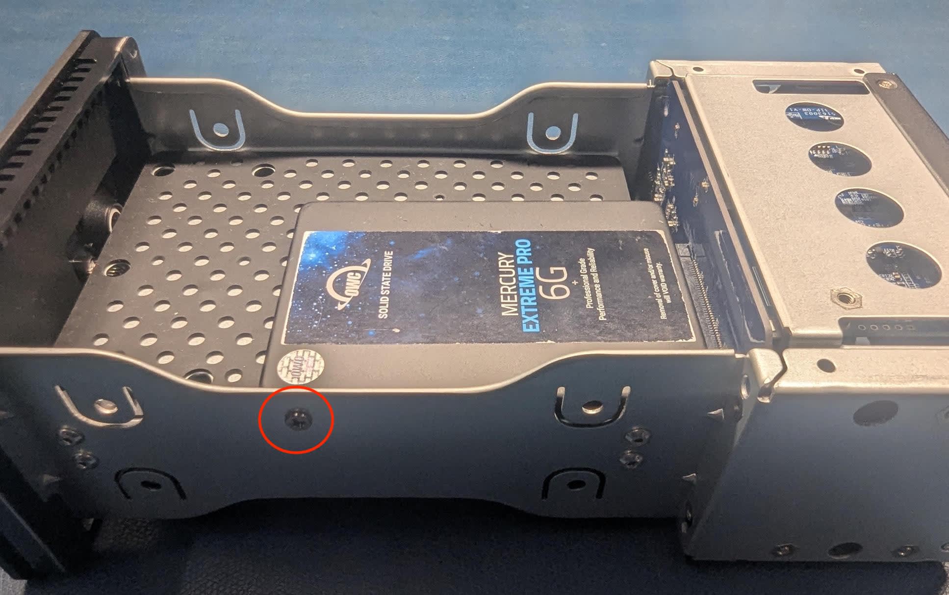
2. Affix the drive to the inner chassis. Holes for 2.5” drive screw is circled in red.
- NOTE: Only (2) drive screws are required for 2.5” drives, (1) drive screw for each side.
- NOTE: Apply slight pressure from the backside of the drive while turning the drive screw to help secure the drive properly.
- NOTE: Do not over tighten the drive screw. Over tightening can cause unnecessary tension on the drive at the connector.
3. Carefully turn the device to the other open drive bay. Carefully seat the drive. The drive label should be visible and minimal force is required.
Closing the Enclosure
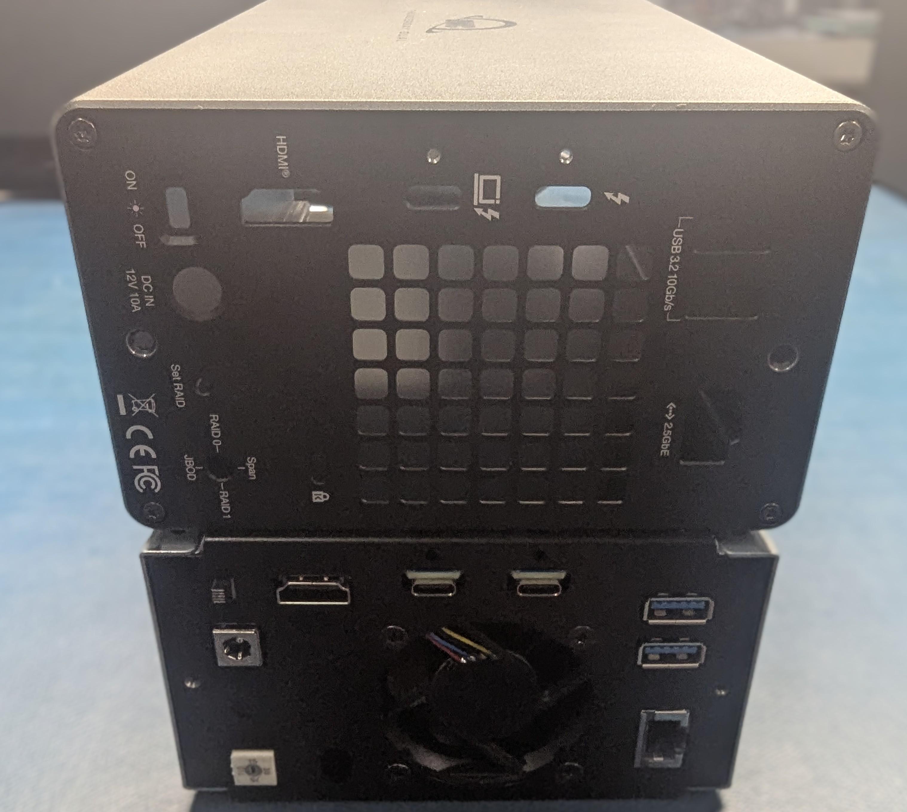
1. Ensure the ports on the back of the inner chassis and the port cut-outs on the back of the outer enclosure are oriented the same way, then slide the inner chassis into the outer enclosure so that the chassis’ front plate is flush with the cover’s front edge.
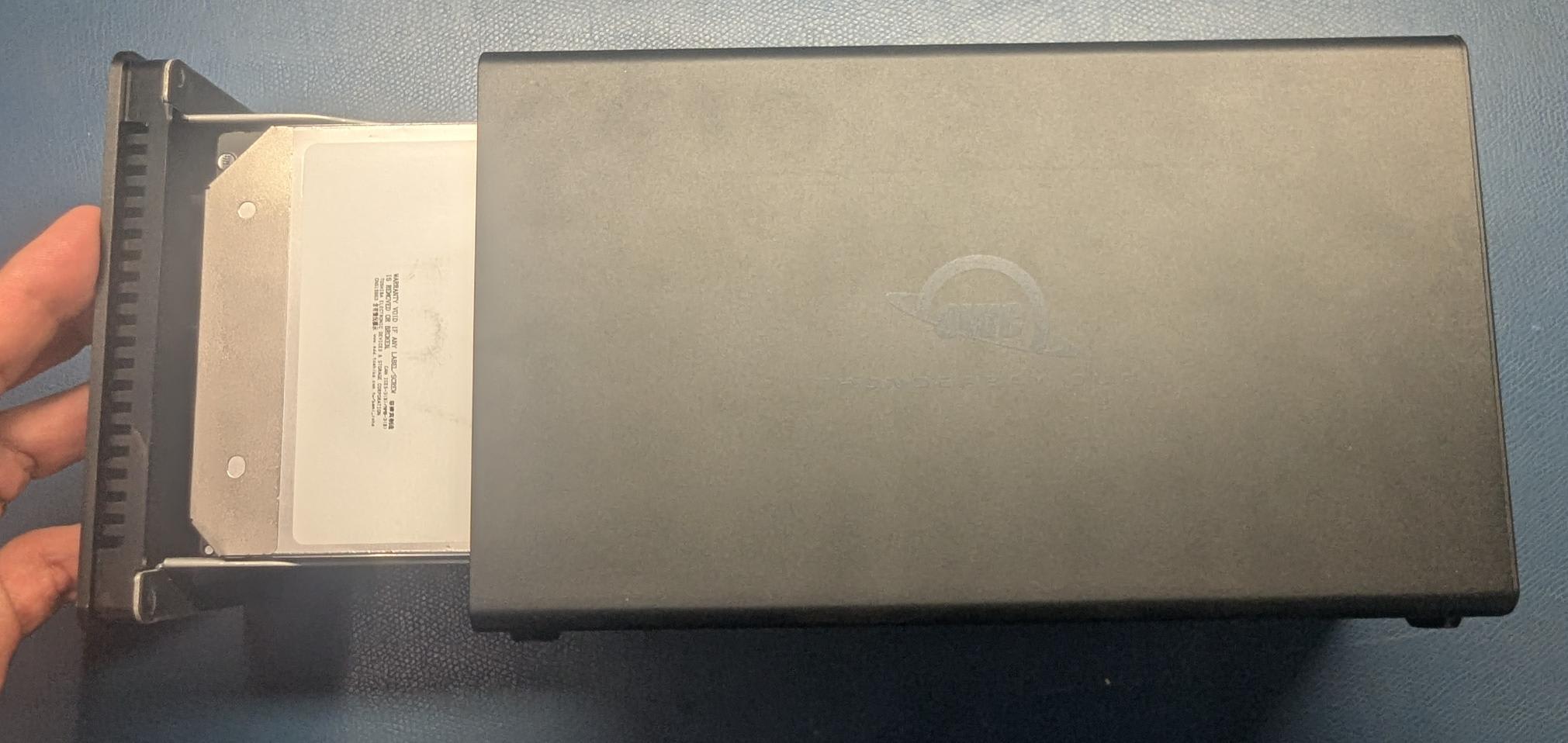
2. Secure the outer and inner chassis using the screws removed earlier.
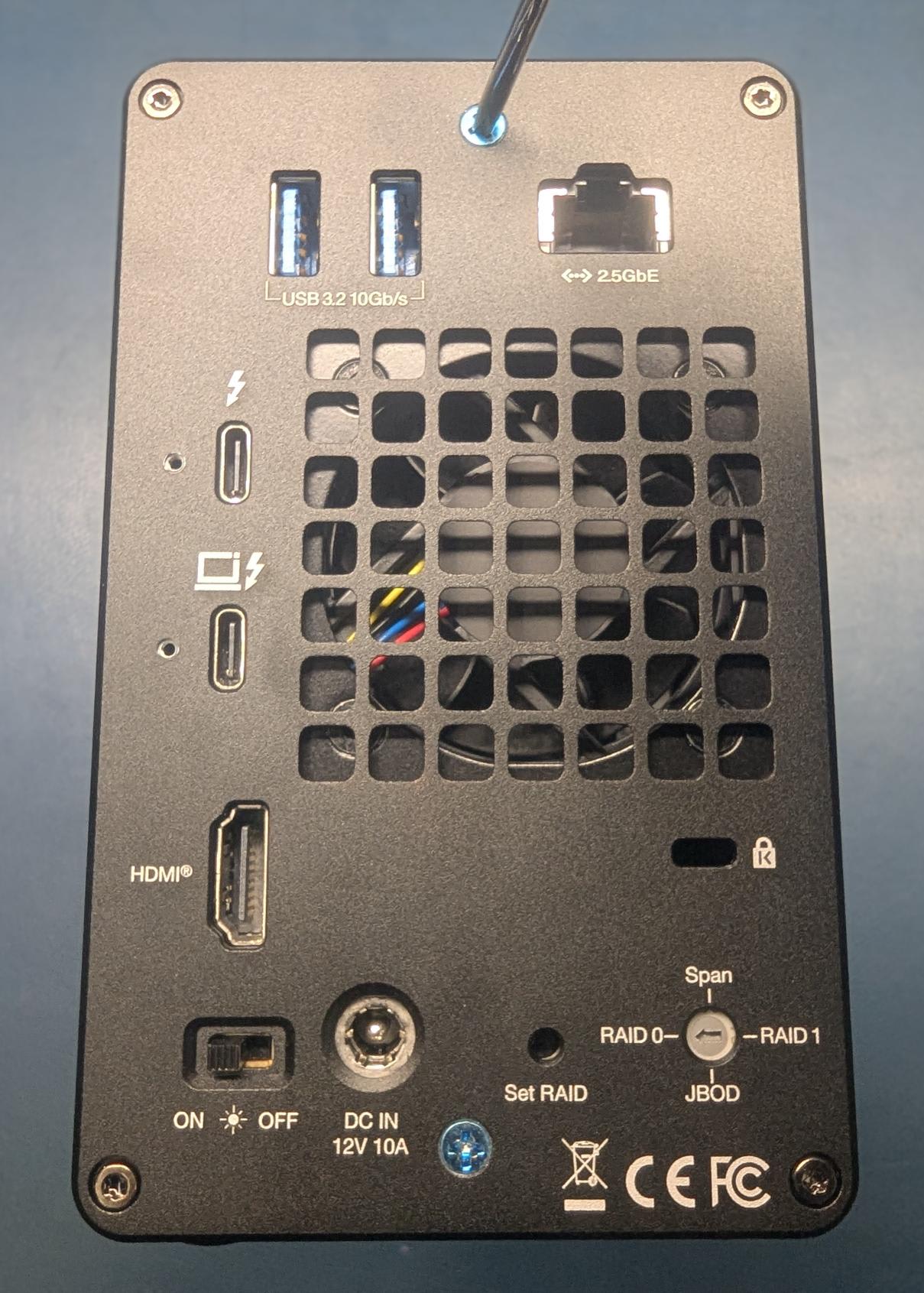
3. The installed drives are ready to be formatted. Please move onto Section 2.4 "Hardware RAID Configuration" or Section 2.5 “Software RAID Configuration Options” for instructions on how to format and configure the OWC Thunderbolt 5 ThunderBay Dual.
2.4 Hardware RAID Configuration
This section describes the process of configuring or reconfiguring the OWC Thunderbolt 5 ThunderBay Dual RAID mode.
NOTE: If there is any data on the drives being installed, changing the RAID mode will result in data loss.
NOTE: Hardware RAID configurations are not supported with NVMe U.2 SSDs. NVMe U.2 SSDs can be formatted as an individual drive.
- Plug the power cable into the OWC Thunderbolt 5 ThunderBay Dual DC IN power port located on the back and into a power outlet. The Power LED will illuminate a solid white.
- Connect the included Thunderbolt cable into one of the two Thunderbolt 3 ports located on the back of the OWC Thunderbolt 5 ThunderBay Dual and into a system. The Power LED will illuminate a solid blue.
NOTE: The OWC Thunderbolt 5 ThunderBay Dual has (2) 40Gb/s Thunderbolt 3 ports with 27W Dynamic Power Delivery. 27W of power is delivered to the first connected system or device. 15W of power is delivered to the second connected system or device. - Select the desired RAID mode by rotating the RAID dial using a paper-clip or flat-head screwdriver. You should feel al slight click each time the arrow is aligned with a new RAID mode.
- The RAID mode is controlled by a dial near the bottom-right corner on the rear plate, in combination with the RAID set button which is just to the left of the dial.
- Once the RAID mode has been selected, using a paper-clip or pin, press and hold the RAID Set button for 3-5 seconds. The RAID mode will be set after releasing the button and the volume(s) are ready to be formatted.
NOTE: The button should remain pressed until the new volume(s) appear on the Desktop and/or a notice is displayed to format the new volume(s).- PC Users: The new volume(s) should appear in Disk Management.
- Mac Users: The new volume(s) should appear in Disk Utility and a notice will be displayed to format the new volume(s).
- Formatting information is available by visiting go.owc.com/storage/formatting.
RAID 0 “Drive Striping” Mode
- The two drives show up as a single large disk with a size equal to the combined capacities of both drives. RAID 0 is used when speed is the primary objective; it does not provide data redundancy for protection. The reading and writing of data files are spread across both drives to gain speed by distributing the workload. This allows for the fastest data transfer rates, but if one drive fails the whole array becomes corrupted. The data will be lost.
- Identical SATA drives (model, capacity, firmware) are required.
- Not supported with NVMe U.2 drives.
RAID 1 “Drive Mirroring” Mode
- The two drives show up as a single disk with a size equal to the capacity of a single drive from the array. RAID 1 copies (or “mirrors”) the data from the first drive to the second drive. This is useful when reliability and redundancy are more important than capacity or maximum speed. When one drive fails, it can be replaced, and the data can be rebuilt automatically from the other functioning drive. See Section 2.5 “Replacing Drives” for more details on the drive replacement and rebuild process.
- Identical SATA drives (model, capacity, firmware) are required.
- Not supported with NVMe U.2 drives.
Span Mode
- Both drives show up as a single large disk, but one which functions differently than RAID 0. The total size will depend on the drives installed; unlike RAID 0 or RAID 1 you can use drives of different capacities. A span is an array (but not a RAID) in which the data is written sequentially across the drives. When one drive becomes full, subsequent data is written to the second drive. This combines the capacities of the drives, but it does not provide any performance or data redundancy benefits.
- Not supported with NVMe U.2 drives.
Independent Drive Mode
- Each drive will appear individually without being combined. If you are using U.2 SSDs, drives of differing capacity and model, or if you are using only one drive, this is the mode to use. The Red LED indication for missing or failed drives is disabled for U.2 drives and drives used in Independent Mode.
2.5 Software RAID Configuration Options
OWC SoftRAID RAID Configuration
Mac OWC SoftRAID Setup
- Download OWC SoftRAID for Mac.
- Please review and follow the steps outlined in OWC SoftRAID Installation for Mac.
- Please review and follow the instructions outlined in Creating a macOS OWC SoftRAID Volume.
Windows OWC SoftRAID Setup
- Download OWC SoftRAID for Windows
- Please review and follow the steps outlined in OWC SoftRAID Installation for Windows.
- Please review and follow the instructions outlined in Creating a Windows OWC SoftRAID Volume.
Mac RAID Configurator
- Open the “Disk Utility” application on your Mac.
- Choose “File” and select “RAID Assistant”.
- Select a set type:
- Striped (RAID 0) set: A striped RAID set can speed up access to your data. You can’t create a RAID set on your startup disk; you must first start up your computer from another disk.
- Mirrored (RAID 1) set: Protect your data against hardware failure with a mirrored RAID set. When you create a mirrored RAID set, your data is written to multiple disks so the information is stored redundantly. You can’t create a RAID set on your startup disk; you must first start up your computer from another disk.
- Concatenated (JBOD) set: Increase storage space with a concatenated disk set. If you need one large disk, but you have several smaller disks, you can create a concatenated disk set to use as one large disk.
- Select the checkboxes of the disks you want to include in the set.
- For each disk, click the pop-up menu in the Role column and choose “RAID slice” or “Spare” to designate the disk as a standard member or spare in the set, then click Next.
- Enter a name for the RAID set in the RAID Name field.
- Click the Format pop-up menu, then choose a volume format that you want for all the disks in the set. (See File system formats available in Disk Utility.)
- Click the “Chunk size” pop-up menu, then choose a disk chunk size that you want used for all the disks.
NOTE: When you create a striped set, chunks of data from the same file are distributed across the drives. Ideally, you want data distributed across drives evenly and at an optimum size so that it can be efficiently accessed. If you want high data throughput from your set, choose a smaller chunk size so that data is spread across the drives and one drive can be accessing data while another is seeking the next chunk. With mirrored disk sets, choose a chunk size that matches the data you’re accessing. For example, when working with video files, your Mac is accessing large chunks of data, whereas when using a database of many small records, your disks may be accessing smaller chunks of information. - If you are creating a mirrored RAID set, select the “Automatically rebuild” checkbox to allow the set to be automatically rebuilt when member disks are reconnected
- Click "Create" and then click "Done".
Device Management
3.1 Drive Failure
- If one of the SATA drives in a Hardware RAID 1, 0, or Span fails (or is missing or not connected properly), the corresponding drive LED on the front of the device will light up a solid red.
- If the OWC Thunderbolt 5 ThunderBay Dual is set up as a RAID 1, a drive that has failed can be replaced to rebuild the array. The data will remain accessible via the functioning drive until the array is rebuilt with a new drive.
- If the OWC Thunderbolt 5 ThunderBay Dual was configured as a Hardware RAID 0:
- The data is lost if a drive failed.
- The data can be recovered if the enclosure has failed. NOTE: The replacement enclosure must be the exact same OWC Thunderbolt 5 ThunderBay Dual model and matching RAID mode must be set before moving drives. Older OWC Thunderbolt 5 ThunderBay Dual models had a black ethernet port on the back, while newer OWC Thunderbolt 5 ThunderBay Dual models have a yellow ethernet port. Please contact support for assistance and warranty details.
- When in Span, only the data stored on the failed drive is lost, although data recovery software will be required to retrieve the data from the other drive.
- If the drives were configured into Independent mode, then the data on the drive that did not fail will remain intact.
3.2 Replacing Drives
- NOTE: Opening the OWC Thunderbolt 5 ThunderBay Dual if pre-built (drives installed from factory) will VOID the warranty. If you wish to remove or replace the drives after the expiration of the original warranty, you may do so at that time.
- A failed drive must be replaced with an identical drive (model, capacity, firmware)
- The OWC Thunderbolt 5 ThunderBay Dual needs an active data signal to remain powered on. If it is disconnected from the computer, or if the computer goes to sleep or turns off, the device will power off. To minimize the rebuild time, it is recommended to keep the device connected to the computer (with the computer powered on), and disable any drive sleep settings on the computer for the duration of the rebuild. While rebuilding, the Drive LED indicator of the original drive has a slow pulsing green light, and the Drive LED indicator of the new drive will light up a solid red. The Drive LED indicator statuses will return to normal once the rebuild process is complete.
- If the Thunderbolt 5 ThunderBay Dual is set up as a RAID 1, a drive that has failed can be replaced to rebuild the array. The data will remain accessible via the functioning drive until the array is rebuilt with a new drive.
- Drive failures configured as a RAID 0, Independent, or Span don’t have a rebuild option and the data is lost. If the enclosure was purchased with drives and it is still under warranty, contact OWC technical support for assistance (see Section 4.4 “Contacting Support”).
- Enclosure failures configured as a RAID 0, Independent, or Span can have the data recovered. Move the drives to another matching OWC Thunderbolt 5 ThunderBay Dual model preset to the drive RAID configuration.
- NOTE: Older OWC Thunderbolt 5 ThunderBay Dual models have a black ethernet port on the back | Newer OWC Thunderbolt 5 ThunderBay Dual models have a yellow ethernet port.
3.3 OWC Disk Performance
As of Windows 10 v. 1809 the default Disk Removal Policy is ‘Quick removal’ instead of ‘Better performance’.
NOTE: OWC storage solutions that are experiencing slow read/write speeds should consider checking and changing the Windows disk removal policy. Changing from "Quick removal" to "Better performance" can increase disk performance. OWC offers the application OWC Disk Performance to help change the Disk Removal Policy. Changing from "Quick removal" to "Better performance" can also be changed through OWC SoftRAID or manually through the operating system.
Please review the support article Storage Solutions: OWC Disk Performance for additional details.
3.4 Manually Unmounting Volumes
To ensure no data is lost during normal use, always eject or unmount the corresponding volume(s) from the operating system before powering off and disconnecting the device. Unmounting options are provided below.
macOS
- Drag the icon for the device you wish to unmount to the trash can; OR
- Right-click the device icon on the desktop, then click “Eject”; OR
- Highlight the device on your Desktop and press Command-E.
Windows
- Windows 10 build 1809 (October 2018) or later:
- Eject the drive by clicking the ‘Show hidden items’ menu in the Taskbar, then clicking ‘Safely Remove Hardware and Eject Media’, and last select the ‘Eject’ option for this volume.
- Windows 10 build 1803 and earlier:
- Go to the System Tray (located in the lower right corner of your screen). Click on the “Eject” icon (a small green arrow over a hardware image).
- A message will appear, detailing the devices that the “Eject” icon controls, i.e., “Safely remove...” Click on this prompt.
- You will then see a message that says, “Safe to Remove Hardware.” It is now safe to disconnect the device from the computer.
3.5 OWC Innergize Software
A software application included with OWC Atlas media cards that currently provides three basic functionalities to the user: Health, Sanitize and Field Firmware Upgradability.
- The Health function allows the user to know how much life is left on their OWC Atlas media card
- Sanitize removes ghost data on OWC Atlas media cards which will allow the media cards to perform at their peak and out of factory condition performance in matter of seconds
- Field Firmware upgradability allows OWC to deliver live updates to our memory cards without the hassle of sending them in for an update.
Installing OWC Innergize
- Download OWC Innergize application based on the system:
- Open the downloaded Innergize.dmg file to begin and complete the installation process.
- For additional information regarding OWC Innergize please consult the support manual "OWC Innergize User Guide"
3.6 Usage Notes
- Identical SATA drives (model, capacity, firmware) are required for RAID 1 and RAID 0 configurations.
- Hardware RAID configurations are not supported with NVMe U.2 SSDs. NVMe U.2 SSDs can be formatted as an individual drive.
- U.2 drive performance will depend on the used drive bay.
- U.2 interface in Drive Bay A is PCIe x1 (770MB/s benchmarked performance).
- U.2 interface in Drive Bay B is PCIe x2 (1512MB/s benchmarked performance).
- Requires 2.5Gbs Ethernet compatible hardware components and cabling (Cat 5e cable minimum, Cat 6 or later strongly recommended).
- The cable type, i.e Cat5e, Cat 6a, is a silkscreen located physically on the cable. Inspecting the cable will help you identify the cable type.
- Windows 10 and Windows 11 users utilizing the OWC Thunderbolt 5 ThunderBay Dual (2.5GbE) ethernet require a network driver.
- OWC Thunderbolt 5 ThunderBay Dual must be connected to a host system via Thunderbolt (USB-C), and cannot be connected over the Ethernet port. The Ethernet port provides the host system with a 2.5GbE network connection through the Thunderbolt (USB-C) connection, and cannot be used to access the drives over a network.
- Use of HDMI display via thunderbolt port requires USB-C to HDMI adapter. (Sold separately at go.owc.com/nwt/usbchdmiadapter.).
- USB ports on the back of the OWC Thunderbolt 5 ThunderBay Dual are backwards compatible with USB 3.0 and USB 2.0 devices.
- Thunderbolt/Thunderbolt 2 device compatibility requires a certified Thunderbolt 3 (USB-C) to Thunderbolt 2 (mDP) adapter and a Thunderbolt 2 cable.
- Compatibility and performance will be at Thunderbolt/Thunderbolt 2 speeds. (Sold separately at go.owc.com/apple/tb3tb2adapter).
- Experienced display support will vary among systems. Please consult the system manufacture specifications to determine the maximum supported resolution, refresh rate, color depth, and number of external displays over Thunderbolt.
- The OWC Thunderbolt 5 ThunderBay Dual has (2) 40Gb/s Thunderbolt 3 ports with 27W Dynamic Power Delivery. 27W of power is delivered to first connected system or device. 15W of power is delivered to the second connected system or device.
- 1229MB/s write, and 1512MB/s read peak performance with 1 x 2.0TB Western Digital U.2 SSD in OWC Thunderbolt 5 ThunderBay Dual PCIe x2 bay connected to a 13-inch MacBook Pro 2016 (MacBookPro13,2) with 8GB RAM and 2.9GHz processor running AJA System Test (4K-Full resolution, 16GB file size, 16 bit RGBA codec, single file test).
Support Resources
4.1 Troubleshooting
- Begin by verifying that the power cable is connected to the OWC Thunderbolt 5 ThunderBay Dual and to a power source. If the power cable is connected to a power strip, make sure that the power strip switch is in the ON position. Next, verify that each end of the data cable is properly plugged into the computer and the OWC Thunderbolt 5 ThunderBay Dual, respectively. If you are still having trouble, try connecting a different Thunderbolt 3 cable and see if the OWC Thunderbolt 5 ThunderBay Dual works properly; you can also connect the device to a different computer.
- If one of the drive LEDs (Drive 1 or Drive 2) lights up a solid red, then that drive has failed, is not fully connected, or is missing. If you purchased the OWC Thunderbolt 5 ThunderBay Dual as an empty enclosure, or the enclosure shipped with drives installed but is past the three-year warranty period, unmount the disk from the OS, power off, and replace the drive as outline d in Section 2.3 “Assembly Steps”. If the OWC Thunderbolt 5 ThunderBay Dual is configured as a RAID 1 and the rebuild LED is pulsing, please wait for the rebuild process to complete. If the rebuild LED is still blinking after more than 48 hours, or if you still need assistance for other reasons, please contact our Support team.
- If issues continue to occur, please know that OWC support is here to help. Contacting support information can be found in Section 4.4. Please have your serial number ready which is located on the bottom of the OWC Thunderbolt 5 ThunderBay Dual and printed on the original packaging
4.2 Online Resources
Product Pages
- OWC Thunderbolt 5 ThunderBay Dual Product Page
- Apple Thunderbolt 3 to Thunderbolt 2 Adapter Product Page
- NWT USB-C to HDMI Display Adapter Product Page
- OWC ClingOn Stabilizer Mount Product Page
- OWC Innergize Product Page
Support Articles
- SoftRAID Knowledgebase
- SoftRAID Mac to Windows Support Article
- Drive Formatting Support Article
- Data Migration Support Article
Support Guide
4.3 About Data Backup
To ensure that your files are protected and to prevent data loss, we strongly suggest that you keep two copies of your data: one copy on your OWC Thunderbolt 5 ThunderBay Dual and a second copy on either your internal drive or another storage medium, such as an optical backup, or on another external storage unit. Any data loss or corruption while using the OWC Thunderbolt 5 ThunderBay Dual is the sole responsibility of the user, and under no circumstances may OWC, its parents, partners, affiliates, officers, employees, or agents be held liable for loss of the use of data including compensation of any kind or recovery of the data.
4.4 Contacting Support
4.5 About This Manual
The images and descriptions may vary slightly between this manual and the unit shipped. Functions and features may change depending on the firmware version. The latest product details and warranty information can be found on the product web page. OWC’s Limited Warranty is not transferable and
General Use Precautions
- To avoid damage, do not expose the device to temperatures outside the following ranges:
- Environmental (Operating)
- Temperature (ºF): 41º — 95º
- Temperature (ºC): 5º — 35º
- Environmental (Non-Operating)
- Temperature (ºF): -4º — 140º
- Temperature (ºC): -20º — 60º
- Environmental (Operating)
- Always unplug the device from the electrical outlet if there is a risk of lightning or if it will be unused for an extended period-of-time. Otherwise, there is an increased risk of electrical shock, short-circuiting, or fire.
- Protect your device from excessive exposure to dust during use or storage. Dust can build up inside the device, increasing the risk of electrical shock, short-circuiting, or fire.
- Do not block any ventilation openings on the device. These help to keep the device cool during operation. Blocking the ventilation openings may increase the risk of electrical shock, short-circuiting, or fire.
Safety Precautions
- Use proper anti-static precautions when handling this device. Failure to do so can increase the risk of electrical shock or short-circuiting.
- Never expose your device to rain, or use it near water, or in damp wet conditions. Never place objects containing liquids on the device, as they may spill everywhere and into the openings. This will increase the risk of electrical shock, short-circuiting, fire, or personal injury.
- To avoid any risk of electrical shock, short-circuiting, fire, or dangerous emissions, never insert any metallic object into the device.
- Please cease use of the device and contact OWC Support if it appears to be malfunctioning.
Terms & Conditions of Sale
Warranty
OWC’s products are subject to OWC’s Terms & Conditions of Sale located at Terms of Sale or other applicable terms. The OWC Thunderbolt 5 ThunderBay Dual comes with a 3-Year Limited Warranty when sold with drives, and a 1-Year Limited Warranty when sold without drives. Additional warranty information can be viewed by visiting Hardware Warranties.
Changes
The material in this document is for information purposes only and subject to change without notice. While reasonable efforts have been made in the preparation of this document to assure its accuracy, OWC, its parent, partners, affiliates, officers, employees, and agents assume no liability resulting from errors or omissions in this document, or from the use of the information contained herein. OWC reserves the right to make changes or revisions in the product design or the product manual without reservation and without obligation to notify any person of such revisions and changes.
FCC Statement
Warning! Modifications not authorized by the manufacturer may void the user’s authority to operate this device.
NOTE: This equipment has been tested and found to comply with the limits for a Class B digital device, pursuant to Part 15 of the FCC Rules. These limits are designed to provide reasonable protection against harmful interference in a residential installation. This equipment generates, uses and can radiate radio frequency energy and, if not installed and used in accordance with the instructions, may cause harmful interference to radio communications. However, there is no guarantee that interference will not occur in a particular installation. If this equipment does cause harmful interference with radio or television reception, which can be determined by turning the equipment off and on, the user is encouraged to try to correct the interference by one or more of the following measures:
- Reorient or relocate the receiving antenna.
- Increase the separation between the equipment and receiver.
- Connect the equipment to an outlet on a circuit different from that to which the receiver is connected.
Copyrights and Trademarks
No part of this publication may be reproduced, stored in a retrieval system, or transmitted in any form or by any means, electronic, mechanical, photocopying, recording or otherwise, without the prior written consent of OWC.
© 2023 Other World Computing, Inc. All rights reserved. OWC and the OWC logo are trademarks of New Concepts Development Corporation, registered in the U.S. and/or other countries. Mac and macOS are trademarks of Apple Inc., registered in the U.S. and other countries. Thunderbolt and the Thunderbolt logo are trademarks of Intel Corporation in the U.S. and/or other countries. Other marks may be the trademark or registered trademark property of their owners.
Free Support Chat
Our free award-winning support team is ready to answer all of your questions. Technical support is available Monday - Friday: 9AM - 6PM. Customer Support & Sales is available Monday - Friday: 9AM - 6PM. Support is unavailable on U.S. Federal holidays. Talk to a human today.